
Free 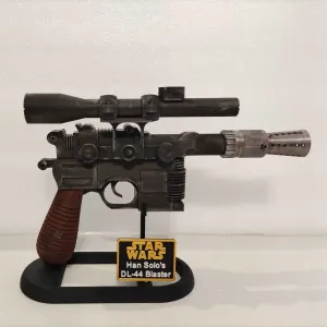
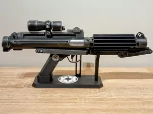
Han Solo DL-44 Blaster - A New Hope Version
Creality Cloud
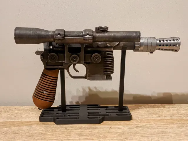
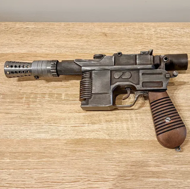
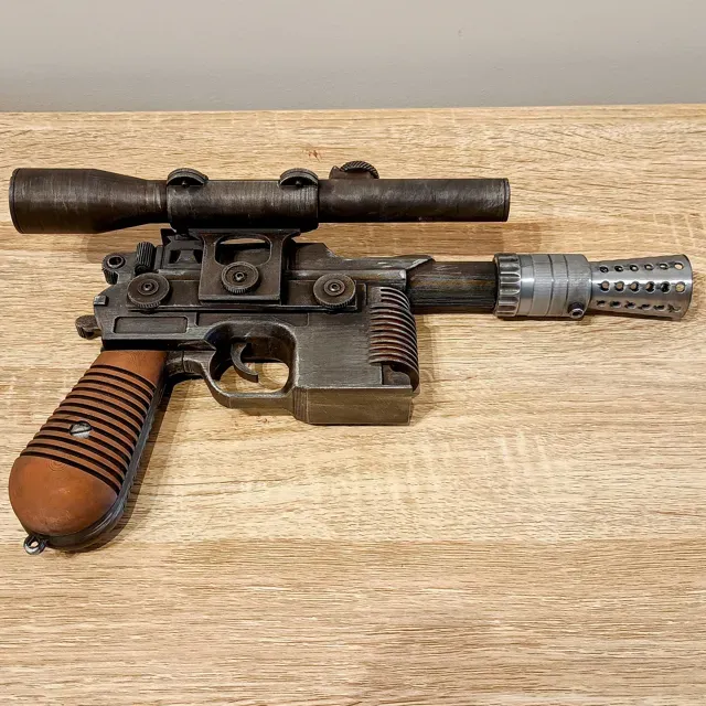
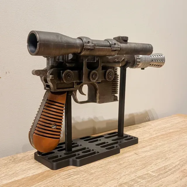
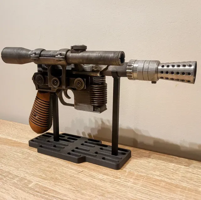
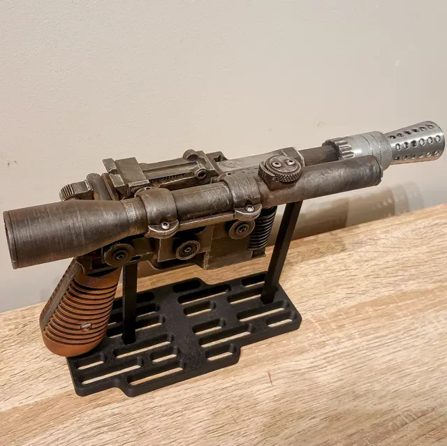
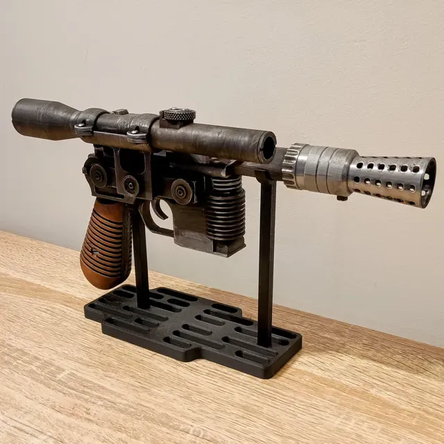
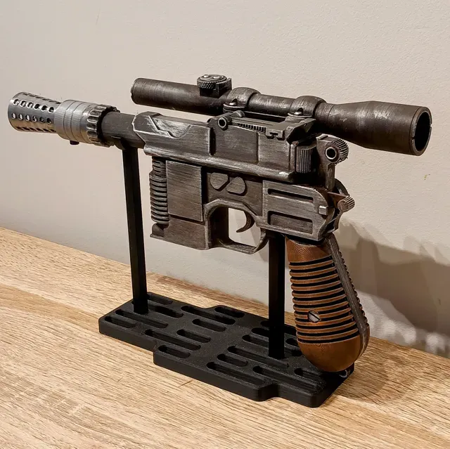
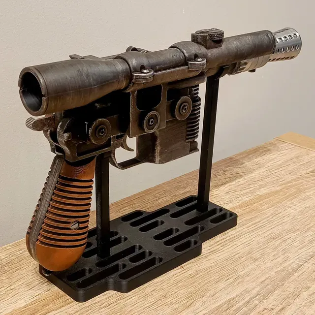
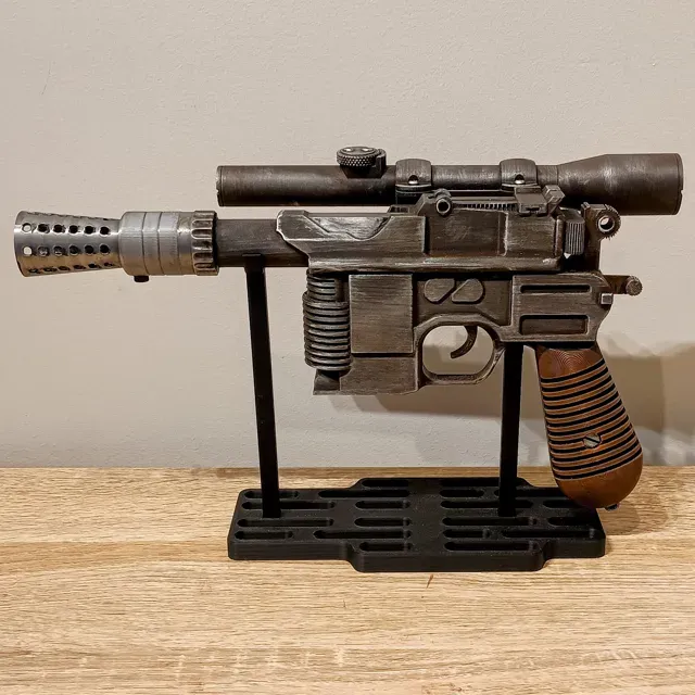
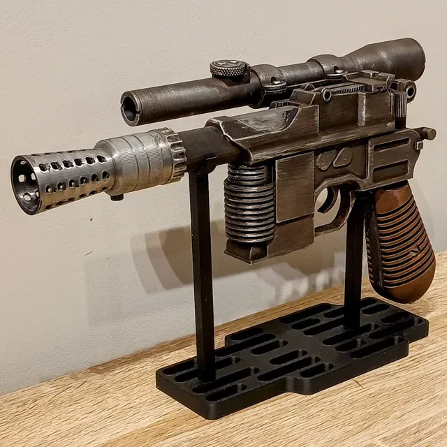
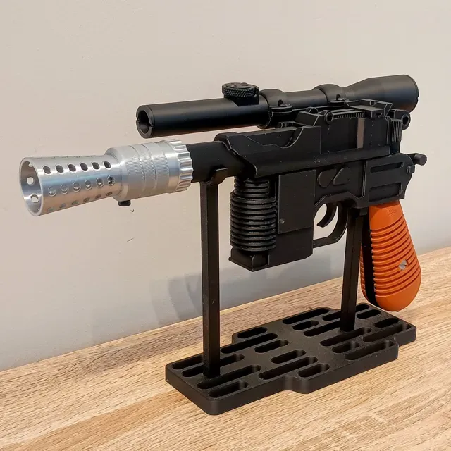
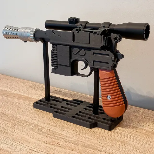
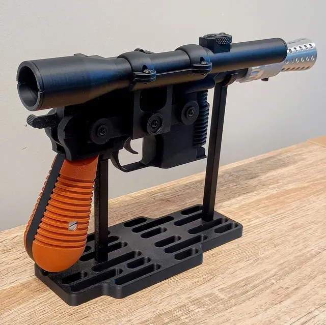
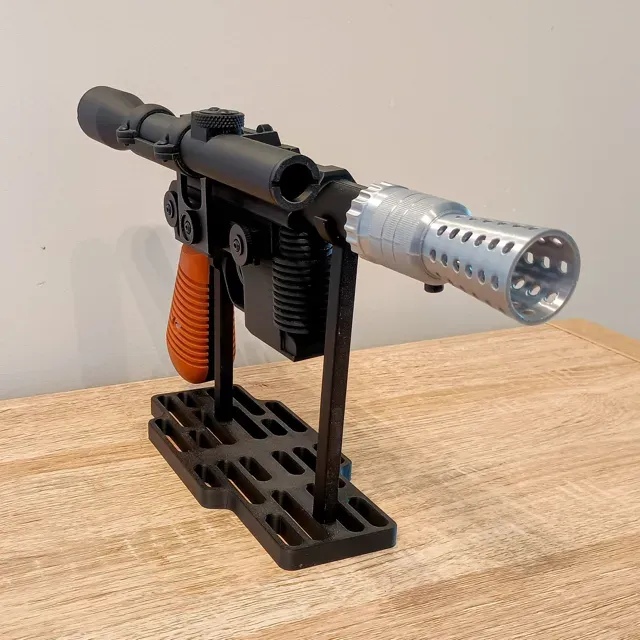
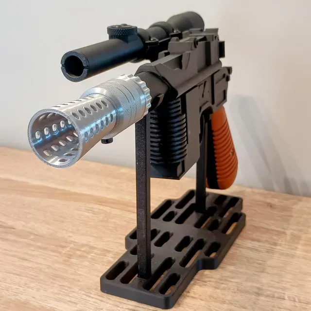
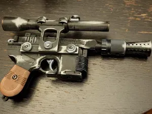
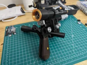
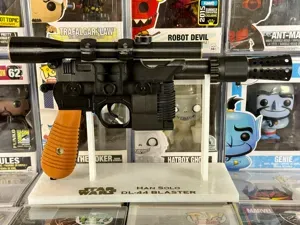
This is a completely new, from-scratch DL-44 ANH build, designed using the Hero DL-44 as reference—while keeping a few tasteful touches I liked from my earlier remix—but this is not a remix . The goal: a version that’s a touch more screen-accurate and still easy to print, assemble, and finish as well as having a spring loaded, movable trigger.
Link to stand https://makerworld.com/en/models/1900274-hero-dl-44-display-stand-with-without-nameplate#profileId-2036482
What’s special
- From-scratch design: fresh geometry, refined proportions, and cleaner joins for a smoother build— not derived from previous meshes. - Moving trigger module: a self-contained trigger box inserts into the main body for reliable, spring-loaded action. The trigger box is intentionally designed as the foundation for a future lights & sound version I’m prototyping. - Color-separated detail parts: knobs, scope bits, and mount details are split so you can print them in silver / bronze / black (they vary across references so print them how you like). You can also print the Grips in Wood PLA and finish with a wood stain. I use Classic Birch Wood PLA with a Satin Walnut Vanish on other prop for a good wood grain effect.
Trigger box (hardware & function)
- Spring: 20 mm length × ~4 mm diameter compression spring (qty 1) - Axle / fastener: M3 × 12 mm - 16mm screw (qty 1) — used as the trigger pivot and to secure the box - Two build paths: - Functional: install the trigger box + spring + M3 screw for a crisp, return-to-rest pull - Static: use the included Non Working Trigger and glue in place Assembly overview
1) Trigger Box (skip for static trigger)
Parts: Left Side Trigger Box, Right Side Trigger Box, Trigger, Trigger Spring (20×4 mm), M3×12 screw.
- Load spring into left half Place the 20×4 mm spring in the spring slot of the Left Side Trigger Box .
- Seat the trigger Drop the Trigger into the left half. It’s easiest if you angle it exactly as shown in the photos —the spring tail should slide into the shallow slot on the trigger .
- Pre-start the axle screw Thread the M3×12 screw into the Right Side Trigger Box from the outside just until 1–2 mm of the tip protrudes inside.
- Join the halves (keyed alignment) Align the Right Side Trigger Box over the left half (it’s keyed ; only fits one way). Apply a small, even pressure and pull the trigger downward slightly— ➤ The pre-started screw tip will pop into the trigger axle bore . When the two halves sit flush , finish driving the screw. Snug, not gorilla-tight.
- Function check Pull and release the trigger several times. It should return crisply with no rub. If sticky, lightly deburr the trigger edges and the axle bore. - Install in Main Body Slide the complete Trigger Box into the Main Body pocket until fully seated.
Static option: Use the Non Moving Trigger instead; align and glue in place later during body closure.
2) Grip Frame & Grips
Parts: Mid Grip, Grip–Main Body Align Pin , Left/Right Grips, Grip Pins, optional real M4 screws or printed heads.
- Join grip to body Glue the Grip–Main Body Align Pin into the Mid Grip . Then glue the Mid Grip to the Main Body (pins and faces make alignment obvious).
- Escutcheons / faux screws Glue your chosen Flat-Head or Phillips printed discs into the grip recesses or use real M4 screws (holes are sized to accept them).
- Grip pins & panels Glue the Grip Pins into the grips. Align the grips to the Mid Grip (use the pins), then glue both grips on.
3) Scope Mount Stack
Parts: Scope Holder, Scope Mount, Scope Holder Offset Bushing, Scope Holder Middle Knob, M3×12–20 screws (3×), Scope Knobs (flat-face or ring-detail variants).
- Mount to holder Glue the Scope Mount to the Scope Holder . There are alignment cutouts —it should sit square without guesswork.
- Bushing to body Glue the Scope Holder Offset Bushing into the Main Body . It keys into cut-out slots on the body—no misalignment possible.
- Middle knob & screw Glue the Scope Holder Middle Knob onto the Scope Mount boss, then drive an M3×12 mm screw through it to secure. - Mount onto bushing Slide the mount assembly onto the bushing on the body and glue. Again, cut-out holes in the mount help you nail alignment. - Side knobs & tie-in screws Glue your chosen Scope Knobs (flat or ring detail) to the sides of the mount. Drive two M3×12–20 mm screws through them into the Main Body —these act as mechanical tie-ins to lock the mount solid.
Color/fastener note: Across references you’ll see black/silver/bronze knobs and various hardware (flat, Phillips, Torx, even rivets). I run black ring-detail knobs with black hex-head screws for a clean hero look.
4) Scope Assembly
Parts: Scope Rear, Scope Front, Scope Top Knob, M3×6–8mm screws (6×), Scope Rings (2× identical).
- Join scope halves Glue Scope Rear and Scope Front together, using the printed seam as your alignment guide. - Top knob Attach the Scope Top Knob with 2× M3×6–8 mm screws. A tiny dab of glue under the knob is optional for belt-and-braces.
- Into holder & rings Glue the finished Scope into the Scope Holder . Then place the Scope Rings over the scope and onto the Scope Mount and fasten with 4× M3×6 mm screws (8 mm also works). ➤ Rings are identical and not handed —orientation doesn’t matter.
5) Barrel & Flash Hider
Parts: Top Barrel, Flash Hider (choose single-screw bottom version or two-screw side version), M4 screw(s).
- Flash hider to barrel Glue the Flash Hider onto the Top Barrel (there are alignment flats). - Single-screw variant: secure with 1× M4 × ~4 mm cap/cheese head from below. - Two-screw variant: secure with 2× M4 Phillips/your choice from the sides (the two-screw style is included as an alternate, per my earlier remix).
- Barrel to body (closure check!) Before gluing the Top Barrel to the Main Body , do a final trigger function check—the barrel closes the body. When happy, glue the barrel in place. 6) Rear Details
Parts: Hammer, Safety Lever.
- Hammer Glue the Hammer into the rear recess. Ensure it sits square in profile. - Safety Glue the Safety Lever in its pocket behind/near the hammer.
That’s your mechanical build complete—time to paint and weather!
Finishing & Weathering
- Aging: acrylic washes ( black, brown, raw umber, burnt sienna ) to punch in recesses. - Edge wear: silver Rub ’n Buff or AK Silver Metallic Wax on high spots and corners. - For technique inspiration, Adam Savage’s approach on Tested is a good north star—layer thin, step back often.
Supports — Why This Orientation (and How to Make It Easy)
The front grille/heat-sink area looks best when printed as modeled , even though it does need supports. Here’s the rationale and how to make removal painless:
0.2mm layer, 2 walls, 15% infill Use standard 0.2mm Profile, some parts need Normal, Snug supports
- Set Main Body xy support offset to 0.65mm
- Variable layer height on Grips
- Silver Silk Parts outer wall slowed to 60mm/s, supports touching build plate only
- Trigger has 8 walls for strength
- Flash Hider, Scope Mount Knobs and Grip Screw plate options, pick you favorite ones
- You can change the knobs and other parts to whatever colour you like- Just have fun with it.
Grill/Heat Sink on main body requires supports, if you don't use Matte PLA make sure you tune your support settings


Names are used only to indicate the source of a result. Polyzon is not affiliated with the listed sites.
Comments 0
Loading comments…