
Free 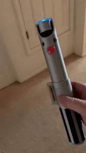
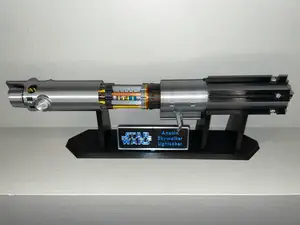
Anakin - The Chosen One Lightsaber
MakerWorld
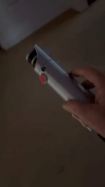
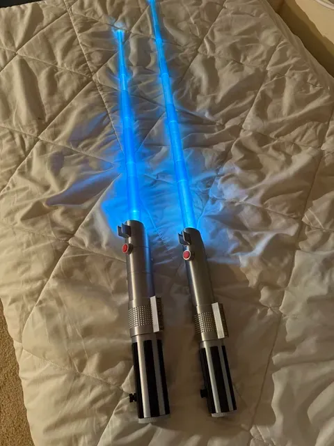
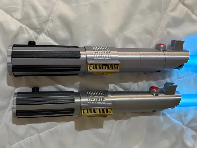
Note: If you like this model, please check out my other Lightsabers: https://makerworld.com/en/collections/14143362-light-sabers
7/7/2026 update: Fix has been implemented. Thanks to @seasoned_mill for identifying the weakness. I made the rotating ring's locking rod thicker. This also required a thicker top so the threads were remove from top and added to middle (going into top). I also rearranged a few of the items on the plates. Hopefully, I have included this on the instructions. I also added more of an offset between the top and the tab, this should make ease the rotation and help make the tab close on its own after multiple movements.
I will post the new profile right after Bambu approves this update.
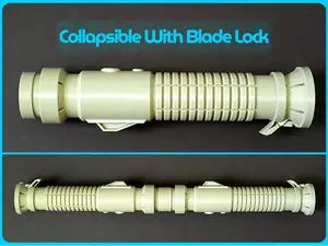
This is a remix of my version of Anakin, The Chosen One, light saber to include a blade locking capability. Like before I used two items not 3d printed. The M4x12 screw for the button on the hilt and I used a 3.5-inch flashlight in the hilt to light up the extended blade. While I did provide a 3d version of the M4 screw, the hole in the hilt will likely not be round enough to secure the button without glue. I used the Hortsun flashlight from Amazon - https://www.amazon.com/dp/B0C9H7CPZM?ref=ppx_yo2ov_dt_b_fed_asin_title&th=1 . Similar flashlights are available but may have slots positioned in slightly different positions.
If you select a different light that is significantly different, if you send me the dimensions I will try to make a holder specially for that light. This is the dimensions for the Hortsun.
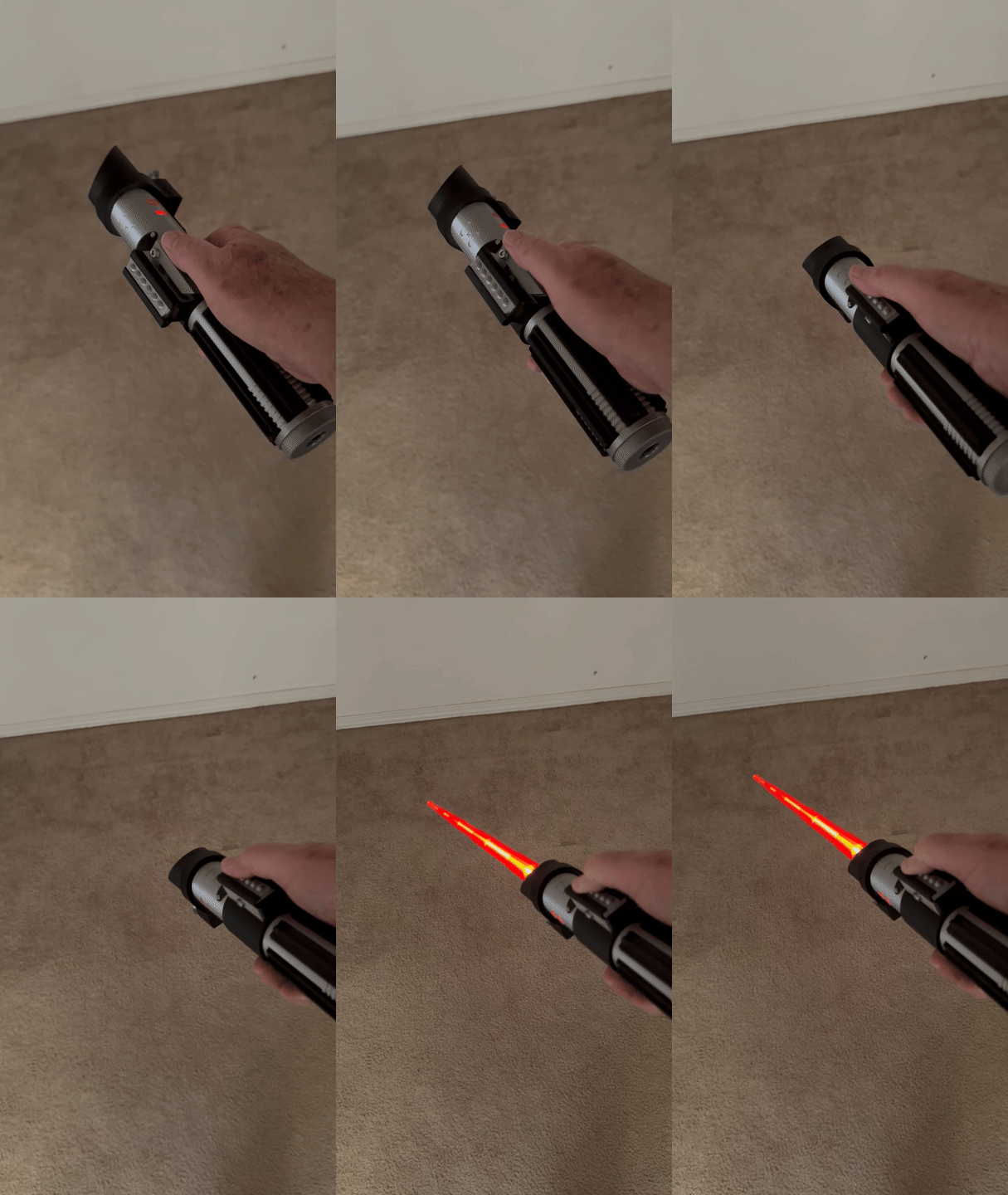
This locking blade version is larger 320mm vs 303mm in length and 46mm vs 40mm in diameter. This was required to insert the rotating blade locking tab. I had to use a rotating release switch instead of the button release I incorporated on my other sabers. While this ring is not present in the original version, I could not implement the sliding button to release the blade, so I had to add the release ring.
The filament used includes silver silk, black, red, gold silk and translucent blue. Except for the blades, I used PLA for the item, and I used PETG for support interface
I try to use treaded pieces for most of the assembly to reduce the requirement for gluing pieces, however some pieces will require glue while other pieces are suggested.
I have several suggestions for printing successfully:
- For the silver silk pieces, I recommend the following settings: Speed: Outer wall speed no more than 50mm/s. I used 50mm/s but it has been demonstrated that a 0.12 height and 30mm/s provide a great surface.
Support:
Type ‘tree’ and Style use the Default, however I changed this to Type “normal” and Style “Default” for the Outer Barrel Front on Plate 3.
PETG as Support/raft interface.
Top interface layers = 3 layers, changed to 4 layers on Plate 3, Outer Barrel Front.
Top interface spacing = 0.5mm
Support/object xy distance = 0.5mm (this greatly helps removing support)
2. I suggest you use a PEI smooth plate instead of the textured plate. The textured PEI plate normally works but the tolerances may vary.
3. I strongly suggest, as I often do, make sure you use an appropriate support interface filament. I normally use PLA as my primary filament and use PETG for the interface.
4. I did not try to optimize or minimize the number of plates. I have provided twelve plates, but this includes an optional print for the gold switch and two plates that can be any filament so you can easily combine plates with similar filament requirements if you like. The twelve plates are provided as the order in which I assembled the light saber.
With the above considered, let’s begin the construction.
Plate 1:
The Front end plus the locking tab and locking ring. The Front end and locking tab pieces are printed together to allow the locking tab to be captured inside the Front end. The tab must be flat on the build plate, Support Type is ‘Tree (auto)’ and Style I used was Default. If you have trouble with removing the support from the threads, then use ‘Tree Slim.’ The support setting of Support/object xy distance = 0.5mm should help in removing the support material. The locking ring is printed with the Front end and tab.
Just a note: while print testing the locking ring I occasionally needed to print just the locking ring, but because of the vertical rod, printing it alone caused issues with vibration during printing which resulted in rough surface that would not fit into the rod slot. The locking ring needs to be printed with another object that is at least as tall as the rod.
Plate 2:
Plate 2 contains just the Middle Section.
Insert the locking ring and its shaft into the Front end, then the Middle section simply screws into the front with the locking ring between them. The locking ring should move slightly, about 18 degrees with a slight click. The Tab will get freer to move the more it is used, but you will likely need to manually put the Tab back in the set (horizontal) position after retracting the blade. The tab needs to be completely closed before you can reset the locking ring.
Plate 3:
Contains the Front-end Outer Barrel and the Emitter Sight. It is shown here for illustration, but wait to install the Emitter sight until you insert the Inner Barrel from Plate 4. I had some issues with getting a clean surface on the Outer Barrel bottom to mate with the Front end. I had better success when I changed the Support Type to be ‘normal’ and Style ‘Default. I also changed the Top interface layers to 4. I slightly increased the offset and this made it easier to
align button slot.
The Front-end Outer Barrel screws onto the Front end. The threads inside the Front-end Outer barrel extend through the button slot. The button will cover this so it is not an issue, but the half-slots for the forward button must align. This will be a tight fit.
The Emitter sight might fit in the tight slot, but it must be glued to stay.
Plate 4:
Contains a single element: the Inner Barrel - emitter, which is suggested to be black and silver. I use my AMS, but this can be printed with a single filament printer by stopping the print when it turns to silver. This part differs from my original in that it has a slot cut out for the locking tab. So, it must fit in the round slot inside the Front-end Outer barrel. Dry fit it first to make sure you have it oriented correctly, then you will need to glue it in place.
Plates 5 and 6:
Plate 5 contains the gold elements: the pins, the switch and switch rocker. The Black bases for the pins are included on Plate 9 with the Ribs and Belt Knob. So, just put the pins aside. Plate 5 has the Switch Center in a solid gold filament. The switch has symbols on the face indented into the switch. I have provided an option on plate 6 which has black inlets into the cut lines. I used the optional plate, but I provide pictures of both pieces. Slide the switch into the middle section, this should have a tight tolerance but should slide in. The rocker switch is then inserted into the switch through the hole in the middle section. This should be tight enough, but you may consider gluing if not tight enough.
Plate 7:
The two front buttons. Both were printed with Silver Silk and Red filament. Both require glue to attach. Once you glue in the tall silver button, this will glue the Inner Barrel Emitter and the Top Section, so make sure you are ready.
Plate 8:
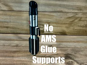
This plate contains three items: the Silver Aft Section Hilt, the End-Cap and the M4x8 screw. This screw is to scale but since the Hilt is printed horizontal, the hole is not always perfectly circular. Therefore, the screw may not fit tightly in the screw hole. You have the option to glue this in to secure the Black button or, like me, I used a real silver M4x8 screw. It will make the hole threads fit – just do not tighten too tight or you will strip the threads. Getting the Hilt threads as clean as possible by screwing them into the other pieces will also help in the removal of support material. The End-Cap will be used after inserting the flashlight. The Aft Section hilt and End Cap with flashlight are connected to the Middle section after you insert the blades.
Plate 9:
New Fix to weak rotaing ring rod I used 0.2mm for layer height but 0.12 will provide more luster to the silver silk.
Speed for Silver Silk should be no higher than 50mm/s, slower = shiny
Use PETG as filament support interface, or vice-versa if using PETG as primary filament.
For support use 3 layers for top interface. I used 4 layers for front outer barrel for smoother support interface surface.
Set the Support/object xy distance to 0.5mm and this will aid in support removal.
Use PEI Smooth plate for best surface.
Fix to stop blade from exiting when flicked too fast There has been some reports that the blade comes all the way out when it is flicked open too fast. I originally design it to slide out with minimum force but I may have been to aggressive so I reduced the diameter of the Top section (need to print Top and Tab together) to 24.8mm so the 25mm blade doesn't come all the out. I am sorry if this requires too much extra printing - depending on if you glued any parts.
If you have issues with the blade coming all the way out - hopefully this solves that issue.


Names are used only to indicate the source of a result. Polyzon is not affiliated with the listed sites.