
Free 
Customizable Round Vent Grill Cover (Parametric)
MakerWorld
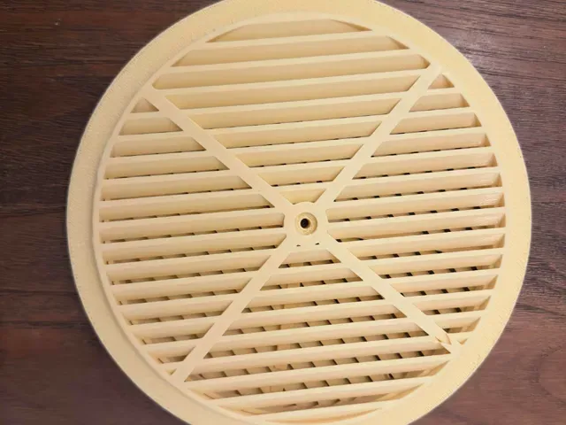
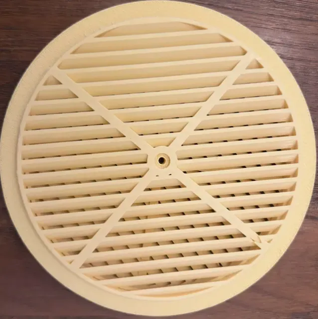
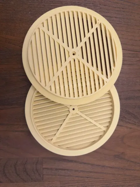
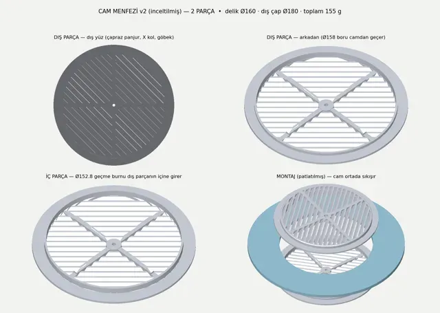
# Two-Piece Window Vent Cover — Ø160 mm Glass Hole / Ø180 mm Face
A printable, direct replacement for the injection-moulded transparent polystyrene **glass vent covers** ("cam menfezi" / gas-appliance ventilation caps) that are fitted into a circular hole cut in a window pane. The original parts become brittle, yellow and crack after a few years of UV exposure, and replacements in the correct size are often hard to source. This model reproduces the original two-shell, single-bolt clamping concept, but with a printable 45° self-supporting louvre geometry, a self-centring spigot and slightly heavier structural sections where they matter.
The vent is **fixed open** — there is no shutter. It provides permanent trickle ventilation while keeping out birds, rodents, leaves and driving rain.
---
## 1. What it fits
| Requirement | Value | |---|---| | Hole diameter in the glass | **Ø160 mm** (nominal). Tolerates Ø159–Ø161 | | Glass thickness | **4.5 – 8.0 mm** (optimum 5 mm, single pane) | | Face diameter (visible) | **Ø180 mm**, both sides | | Overlap onto glass | 10 mm all round, each side | | Protrusion | 8.2 mm outward, 8.2 mm inward from the glass surface | | Hardware | 1 × M4 socket-head cap screw, 20 mm + 1 × M4 hex nut |
**Not suitable for insulated glazing units (double/triple glazing).** The clamping length is designed for a single pane. For an IGU you would need to scale the tube lengths — see §8.
---
## 2. Design features
- **45° inclined louvres, fully self-supporting.** The blades are cut at 45° through a 5 mm deep plate, so every internal surface is at or below the 45° overhang limit. **No support material anywhere on either part** except a small ring under the flange (see §5). - **Near-zero straight line of sight.** Blade pitch 5.5 mm, opening 4.0 mm, plate depth 5.0 mm. The residual straight-through gap is only **0.66 mm**, so wind-driven rain is deflected while airflow is barely affected. - **Self-centring spigot.** The inner part carries a Ø152.8 spigot that slides 7.5 mm into the outer part's Ø154 bore. The two shells align themselves before the bolt is tightened — the commercial original relies on the bolt alone and always sits off-centre. - **Captive hex nut pocket** so the assembly can be tightened one-handed. - **Orientation mark.** A small engraved triangle (▲) sits on one arm of the cross on the outer face of both shells. Both triangles must point **up** — the louvres slope downwards and outwards. - **Cross bracing.** Four radial arms, 7 mm deep near the hub tapering to 5 mm at the rim, carry the bolt clamping load out to the flange ring. - **Silicone-free.** The joint is a mechanical clamp; a soft gasket is recommended but no adhesive is required, and the vent can be removed later.
---
## 3. Dimensions
### Outer part (`menfez_v2_DIS_parca.stl`)
| Feature | Value | |---|---| | Overall | Ø180.0 × 12.2 mm | | Flange | Ø180.0, 2.2 mm thick | | Body / tube | Ø158.0 outer, Ø154.0 bore, wall 2.0 mm | | Tube length past flange | 4.0 mm (enters the glass hole) | | Louvre plate | 5.0 mm deep, Ø153 louvred field, Ø158 rim | | Louvre blade | 1.5 mm thick (normal to blade), 5.5 mm pitch, 4.0 mm opening | | Cross arms | 5.0 mm wide, 7.0 mm deep (r < 60), 5.0 mm deep (r > 60) | | Hub | Ø17, Ø4.4 through hole, Ø9.0 × 3.0 counterbore |
### Inner part (`menfez_v2_IC_parca.stl`)
| Feature | Value | |---|---| | Overall | Ø180.0 × 15.7 mm | | Flange | Ø180.0, 2.2 mm thick | | Body / tube | Ø158.0 outer, Ø154.0 bore, wall 2.0 mm | | Spigot | Ø152.8 outer, Ø148.8 bore, wall 2.0 mm, 7.5 mm long | | Hub | Ø17, Ø4.4 through hole, hex pocket 7.2 mm A/F × 3.2 mm deep |
### Airflow
| | | |---|---| | Clear bore | Ø149 mm = 174 cm² | | Net free area through the louvres | **≈ 121 cm²** (61.9 % of the Ø158 face) | | Straight line-of-sight gap | 0.66 mm | | Largest aperture (animal ingress) | 4.0 × 9.0 mm |
---
## 4. Material, volume and weight
Solid model volume, measured from the watertight meshes (not a slicer estimate — your slicer will report a few percent more because of perimeter overlap).
| | Outer part | Inner part | **Set** | |---|---|---|---| | Model volume | 59.2 cm³ | 62.9 cm³ | **122.1 cm³** | | Filament, 1.75 mm | 24.6 m | 26.2 m | **50.8 m** | | Mass in **PETG** (1.27 g/cm³) | 75 g | 80 g | **155 g** | | Mass in **PLA** (1.24 g/cm³) | 73 g | 78 g | **151 g** | | Mass in **ASA/ASA-CF** (1.07 g/cm³) | 63 g | 67 g | **130 g** | | Triangles in STL | 8 144 | 11 486 | — | | Approx. print time @ 0.20 mm, 0.4 nozzle | ≈ 2 h 15 | ≈ 2 h 30 | **≈ 4 h 45** |
### Material choice
- **ASA — best.** UV stable, 100 °C service temperature. This part sits in direct sun on a window. Needs an enclosure. - **PETG — recommended for open-frame printers.** Good moisture and impact resistance, ~75 °C service temperature, moderate UV resistance. Expect gradual surface chalking after several years, not structural failure. - **PLA — not recommended.** Glass surfaces reach 60–70 °C in summer sun; PLA creeps and the louvres will sag. Acceptable only for a shaded north-facing installation or as a test fit. - Transparent PETG reproduces the look of the original part, but the louvre field will read as frosted rather than clear.
---
## 5. Print settings
Both parts print **louvre face down on the build plate.** The STLs are already oriented; do not rotate.
| Setting | Value | |---|---| | Layer height | 0.20 mm (0.16 mm for a finer louvre finish) | | Nozzle | 0.4 mm | | Wall loops | 3 | | Top / bottom layers | 4 | | Infill | 15 % gyroid (most of the part is solid wall anyway) | | Support | **On build plate only**, normal type, top Z gap 0.2 mm, 60 % density | | Brim | 5 mm — recommended, the footprint is Ø180 and thin at the edge | | Bed | Textured PEI. Glue stick if printing PETG |
**About the support:** the only overhang is the 11 mm wide annular underside of the Ø180 flange, 6 mm above the plate. "Support on build plate only" places a simple ring of support underneath it that snaps off. That surface faces the glass and is hidden in the finished assembly, so witness marks are irrelevant. Everything else — the louvres, the tube, the cross, the spigot — is self-supporting.
Build volume needed: 180 × 180 × 16 mm. Fits any 180 mm+ printer. Both parts fit on a 256 × 256 plate in a single job if your printer handles two objects, but sequential printing is easier.
---
## 6. Hardware
| Item | Spec | Notes | |---|---|---| | Screw | M4 × 20 mm socket head cap (DIN 912 / ISO 4762), A2 stainless | Head Ø7.0 clears the counterbore | | Nut | M4 hex, A2 stainless, 3.2 mm thick | Drops into the 7.2 mm A/F pocket | | Gasket | 2 × ring of 2–3 mm self-adhesive EPDM or felt strip, Ø165 × Ø180 | Strongly recommended |
The commercial original uses a 4 × 40 mm bolt; that length is too long for this design.
---
## 7. Assembly
1. Clean the glass around the hole on both faces. 2. Stick a ring of thin EPDM/felt gasket onto the glass-facing side of **both** flanges. Do not use a hard washer against glass. 3. Drop the M4 nut into the hex pocket in the inner part's hub. 4. From outside, offer the outer part into the hole. The Ø158 tube locates in the Ø160 hole. Rotate until the engraved **▲ points up**. 5. From inside, push the inner part's spigot into the outer part's bore. Again, **▲ up**. 6. Pass the M4 screw through from the outside and tighten with a 3 mm hex key. 7. **Tighten by hand only — do not exceed ≈0.25 N·m.** The plate is checked to 300 N of bolt preload; more than that both overstresses the cross arms at elevated temperature and risks the glass. The clamp only has to hold the shells together; the gasket does the sealing.
### If you cannot reach the outside of the glass
Glue an M4 nut into the Ø9 counterbore of the **outer** part with epoxy and let it cure fully. The screw can then be inserted entirely from the inside, and the hex pocket in the inner part simply acts as a clearance recess for the screw head. This is how the model was installed on a fourth-floor fixed pane.
---
0.2mm layer, 2 walls, 15% infill Print with support.

Names are used only to indicate the source of a result. Polyzon is not affiliated with the listed sites.
Comments