
Free 
Tilt Window Hose Adapter 100mm – 3D Printer & AC
MakerWorld
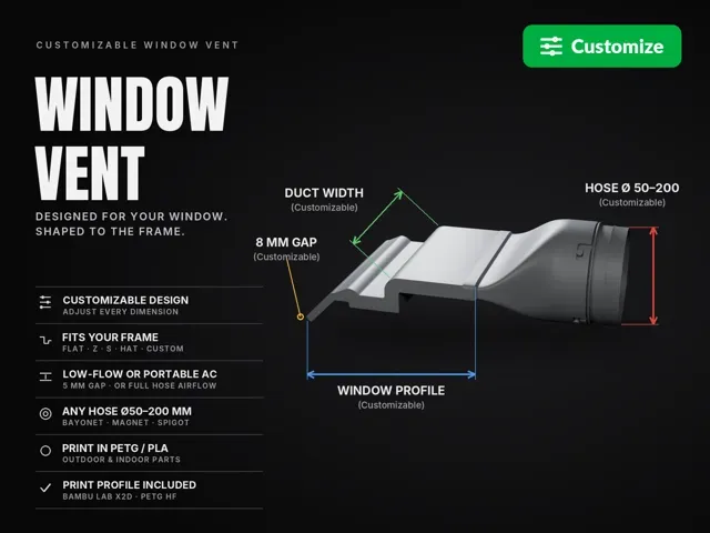
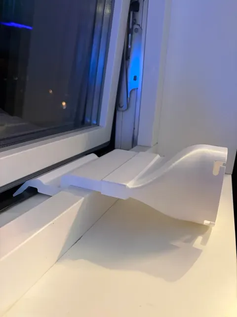
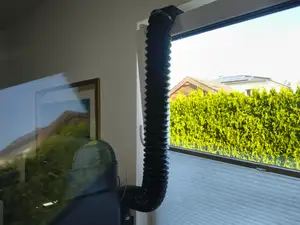
Boost Me If the model solved a problem for you, a Boost would mean a lot – it helps me keep improving this model and making more parametric designs like it. A Make with a photo of your print in the window is just as welcome – Would love to see where it ends up, and it helps others find the model. Thanks! Exhaust a hose (3D-printer enclosure, air purifier, grow tent, portable AC…) through a partly opened window. Instead of a one-size-fits-none adapter, you describe your window frame and the duct is generated to follow it exactly.
WHICH VARIANT DO I NEED?
Choose use_case in section 1 of the customizer:
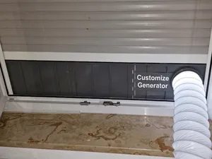
- Low-flow fan (default) – 3D-printer enclosure, air purifier, grow tent. The window opens only a few mm (you set gap_thickness, default 8 mm). This restricts the airflow (default ≈ 12 % of a 100 mm hose) – fine for small fans. - Portable AC – the slot is calculated automatically to get the same air area as the hose , so the airflow is not restricted. The window has to open more: the console shows exactly how much. Using it for a portable AC? Pick Portable AC, set your hose diameter and use a wide duct (duct_width 250 is the max). Approximate window opening:
- 100 mm hose: ≈ 50 mm (duct_width 160) / ≈ 33 mm (duct_width 250) - 125 mm hose: ≈ 77 mm / ≈ 50 mm - 150 mm hose: ≈ 111 mm / ≈ 71 mm A portable AC pushes a lot of hot air – squeezing it through a few-mm slot makes it lose cooling power and can make it overheat. That is why the AC variant needs a wider window opening.
⚠️ Not for tumble dryers. A restricted dryer exhaust collects lint and moisture and is a fire risk.
HOW IT WORKS
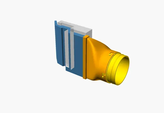
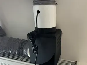
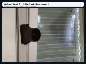
- A - Hose connector + funnel (indoors): Bayonet, Magnetic or Straight spigot, any hose diameter 50-200 mm. - B - Window duct: a flat duct that follows your window frame and passes the window gap (Low-flow: only gap_thickness, default 8 mm – Portable AC: calculated). - C - Hose adapter (bayonet male with 4 pins, or magnetic ring) and D - Cap to close the vent when not in use. - A-B joint: A slides 33 mm over B (joint_depth). 12 crush ribs inside the sleeve give a tight press fit that holds without glue. Tune it with crush_rib_height (default 0.75 mm) and print the Joint test ring first if your printer runs tight or loose. QUICK START
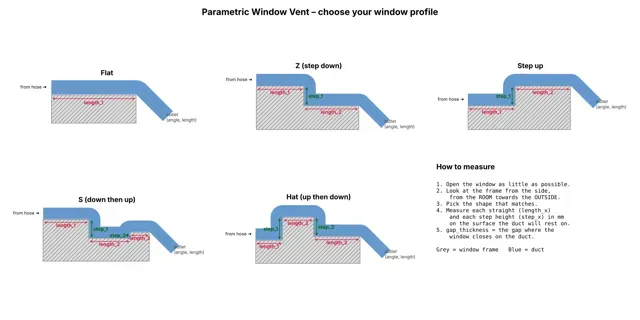
- Click Customize to open the Parametric Model Maker. - Section 1: choose use_case – Low-flow fan or Portable AC (see above). - Section 2: pick your window profile (Flat, Z, Step up, S, Hat or Custom) - see the profile guide image - and enter the lengths and step heights in mm. - Section 3: set how far your window opens (gap_thickness, Low-flow only) and the outlet angle. - Section 4: duct width, walls, joint depth and crush ribs. Section 5: hose diameter and connection type. - Check the Assembly preview (the grey block is your window), then generate part A, B, C and D one at a time. - Print the Test strip (about 10 minutes) and the Joint test ring before the full parts. PRINTING
- B stands on its side (profile on the bed), no supports. Use PETG or ASA - it sits in the window and outdoors. Use a 10 mm outer brim, it is tall and narrow. - A prints mouth-down with supports on the build plate only (included profile). 0.12 mm layers in the bayonet zone (first 27 mm), 0.20 mm above. PLA is fine indoors unless the hose carries hot air. - C prints hose end down, tip up, without supports. The included profile reinforces the pins (3 walls, 50 % infill) and prints them slower for a clean finish. - D prints flat side down without supports. - 2 walls, 15 % infill (3 walls and 50 % infill on the bayonet pins of C). TIPS
- A wider duct gives more air for the same window opening. - Seal the rest of the window gap with foam tape, and use a back-draft damper or the cap in winter. - The bayonet defaults (100 mm, 4 pins, 6 mm pins, 15 degree twist) fit common 100 mm (4-inch) bayonet hose attachments. The included print profile is my own setup: 100 mm hose, bayonet, 160 mm wide S-profile window duct, printed on a Bambu Lab X2D in PETG HF.
COMPATIBILITY
All parts, including the bayonet, are my own design and generated by the included OpenSCAD model. With the default settings the bayonet is dimensioned to fit common 100 mm (4-inch) bayonet hose attachments.
PETG HF – parts A, B, C with reinforced bayonet pins My own setup for the default model: 100 mm hose, bayonet, 160 mm wide S-profile duct, Low-flow use case . Your window is different? Click Customize , enter your own values and print the generated parts – these settings are a good starting point.
BASE SETTINGS
- Bambu Lab X2D, 0.4 mm nozzle, Bambu PETG HF (245 °C nozzle / 70 °C bed) - 0.20 mm Standard, 2 walls, 5 top / 3 bottom layers, 15 % grid infill PLATE 1 – PART A (hose connector + funnel)
- 0.12 mm layers in the bayonet socket (first 27 mm) for an accurate fit, 0.20 mm above - Inner-outer-inner wall order for clean, accurate outer surfaces - Supports on build plate only (0.3 mm top distance) and a 9 mm outer brim PLATE 2 – PART B (window duct)
- Stands on its side with the profile on the bed – no supports - 10 mm outer brim – the part is tall and narrow PLATE 3 – PART C (hose adapter)
- Modifiers on the 4 bayonet pins: 3 walls and 50 % infill for strength - The pins are printed slower (outer wall 40 mm/s, inner wall 60 mm/s) for a clean, accurate finish Part D (cap) is not included – generate it in the customizer if you need it.
Names are used only to indicate the source of a result. Polyzon is not affiliated with the listed sites.