
Free 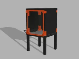
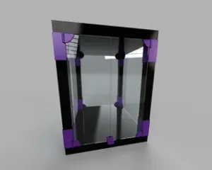
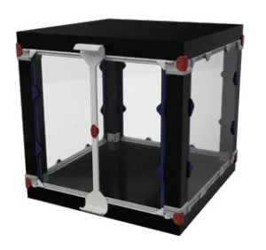
Tall and Beefy Lack Enclosure
Printables
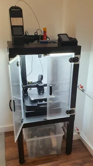
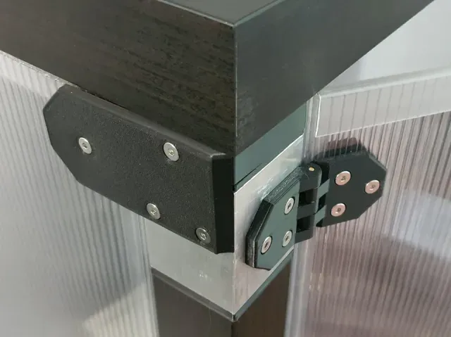

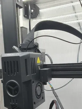
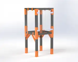
Height can be increased by making aluminium profile sections longer, but don't go shorter than 7cm. With 7cm risers, it's tall enough to fit the printer (with spool holder removed), and has about 8 cm clearance, which you can use to put a paver stone under the printer for inertially damping vibrations. Thickness of side panels can be between 1mm-10mm
These printed parts and BOM are just for the basic enclosure. It goes well with additions such as putting filament spool on top (I keep a filament dryer there), moving the control panel outside, adding lights, etc, but there are many ways to do those things and lots of options. If there is interest in how exactly I did it, let me know, I will upload any relevant files separately.
One thing to keep in mind, the parts are specifically designed for the fasteners I decided to use. They should be easily adaptable to other types (e.g. skipping rivnuts and using sheet metal screws to secure parts directly to the aluminium profile, etc), but you may have to modify the design a bit. Also, possibly, number of fasteners I used is an overkill, feel free to remix and correct that.
BOM
- 2 Ikea LACK tables - 6mm twinwall polycarbonate sheet, transparent, cut into: - 3 44.5cm×58cm panels - 2 22cm×58cm panels - 6mm polycarbonate U-profile, 2m ("6mm" means it's a closing profile for 6mm twinwall sheet) - 50×50×2mm square aluminium profile (50mm on the side, 2mm wall thickness), cut into: - 8 7cm pieces - 8 flathead 6×50mm wood screws, Pozidriv - 40 flathead 3×50mm wood screws, Pozidriv - 26 M4 8L×6OD heat inserts - 48 M4 rivnuts - 12 M4 hex nuts - 14 M4×15mm thin pan head machine screws, hex socket - 72 M4x20mm thin pan head machine screws, hex socket - ⌀3mm metal rod, cut into - 4 40mm pieces - (optional) 16 M3 0,1mm shim washers - 4 ⌀8mm×1mm neodymium magnets - 1mm steel plate, cut into: - 2 5cm×1cm plates - foam backed double sided mounting tape - (optional) 2mm foam rubber tape - (optional) 25mm door sealing tape, 10m (it's basically a rubber or silicone strip with sticky tape on one half of it) Printed parts
- 8 Leg_profile_connector - (optional) 4 Leg_profile_shim - 4 Top_profile_connector_front - 4 Top_profile_connector_rear - 6 Inner_panel_bracket_R - 6 Inner_panel_bracket_R - mirrored in slicer - 6 Outer_panel_bracket_R - 6 Outer_panel_bracket_R - mirrored in slicer - 2 Handle_front - 2 Handle_rear - 4 Hinge_door_back - 4 Hinge_door_front - 4 Hinge_leg - 2 Door_magnet_stop - 4 Door_magnet_mount Printing suggestions
Inner bracket should be printed standing on the edge, not laying on either of the flats - that should help its mechanical strength. There are a lot of screw holes with counterbores here - there is an option to print a sacrificial layer for those in most slicers, which works quite well.
(horrible) Assembly instructions
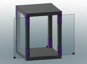
- Assemble one of the LACK tables - Cut the twinwall sheet sheet into panels. Use a metal straight edge and utility knife, you might need to make a couple of cuts (particularly when cutting across the flutes), but it's easier and cleaner compared to using a hand saw IMO. - Cut the aluminium pipe into sections. If using a hacksaw, it's best to cut each wall separately from the top if making a straight cut is a challenge. - Cut the thin metal rod into sections - Cut two 5cm×1cm pieces from the steel sheet - Print out the parts (start with profile connectors and panel brackets) - Insert heat inserts into top_profile_connectors (the rear ones have 4 holes for the inserts, and front ones have 2 holes) and the handles - Cut out circles from foam rubber (or other padding) and stick them in the large shallow circular pockets on the panel brackets, and door hinges. Add a hole for the screw in the middle when needed. - Attach leg_profile_connectors to LACK legs. One side of the leg has a predrilled hole, use the 6mm wood screw for that one (using the center hole on the printed part), other side you need to drill the holes yourself (use the corner holes on printed part; you can probably get away with using just 2 diagonally). One end of the leg has a slight chamfer that really stands out if using a black LACK - if you find it as irritating as I do, you can use leg profile shim to cover it up - Attach top profile connectors to the tabletops so they sit flush with the corners. For the ones that go on top of the lower tabletop, you need to drill some holes; the ones that go on the bottom of the upper tabletop can use pre-drilled holes. Pay attention to the orientation, you need to put connectors with 4 heat inserts on the side of the table which will be the rear of the enclosure, and the ones with 2 inserts on the front side, with the inserts oriented towards outside and the rear - Press fit profile_connectors into aluminium sections, making the basic frame of the enclosure - Attach outer and inner panel brackets using the heat inserts and 15mm machine screws. Mark locations of the remaining holes on the aluminium. Also, use the hinge_leg printed part to mark holes for attaching the hinges to the aluminium. Disassemble the press-fitted legs again (this is a dumb ass way to mark the drill holes - I really should have made or printed some drilling templates, but I didn't, and here we are. Feel free to be smarter than me.) - Drill holes in aluminium, use drill size that matches rivnut diameter exactly or is smaller by 0,1mm - Install rivnuts (you don't really need a special tool for it - look it up) - Once again, attach the legs to the bottom tabletop (but leave the upper tabletop alone for now). Then, attach all outer panel brackets (firmly), and inner panel brackets (loosely) - Insert the side and rear panels. Mark where the outer brackets should attach to them, then take them out, and drill or cut holes in the panel (twinwall is a bit flimsy for drilling - I found a circle punch to work the best for me) - If using the sealing tape (to make the enclosure somewhat less drafty), attach it to all sides of the panel, on the inner side. It should stick out from panel edge just by 2-3mm (if it sticks out too much, it will be pushed on too strongly and can get unglued) - Insert the side and rear panels again, and fix them in place using 15mm machine screws and hex nuts (those go into the pocket on the inner bracket). - Put the upper tabletop on top, press-fit the connectors into the aluminium sections, then secure it to the rest using 15mm machine screws and the uppermost screw holes on the inner and outer bracket (those are in line with heat inserts). This completes the basic frame of the enclosure. - Assemble the hinges - press-fit the metal rod sections as hinge pins (you can tap them lightly with a hammer). If using, put the shim washers between the hinge sections (so that the pin goes through them as well) to avoid plastic-on-plastic friction - Attach the hinges to the legs - Put one of the door panels approximately where it should be, and mark where the holes for attaching it to the hinge should be - Put handle_rear where it should be and mark the holes - Make the holes - those can be slightly larger (about 8mm diameter works well) so that there is wiggle room for fine adjustments - Attach the polycarbonate closing profile to the panel - specifically, to the top and bottom edge (where the flute openings are), and to the inner edge (where the doors meet). Cut it at 45° angle so that the sections join nicely on the outside, but on the inside, cut them at 90° angle so that there is a small square hole between them in the corner (that's where the magnets will go) - If using the sealing tape, affix it to the outer edge (where it will meet the leg) on the inside - Attach the handle, using 20mm screws and sandwiching the panel between handle_front and handle_back - Attach the door panel to the hinges, using 20mm screws and hex nuts (which go into their pockets on the hinge_door_back printed part). Before tightening the screws, adjust position so it sit straight. - Go back to the step after you attached the hinges, and repeat everything for other half of the door - Affix the magnets to door_magnet_mounts, then affix this assembly to the door corner on inner side, using foam-backed tape in both cases - Affix the steel plate to door_magnet_stop with foam backed tape. Close one half of the door, and with the tape affix the stop on the bottom and on the top, so it sits in the middle and at the right depth.




%2Fhttps%3A%2F%2Ffbi.cults3d.com%2Fuploaders%2F13539655%2Fillustration-file%2Fbca1aa77-3b52-4646-9a20-e116f21749b1%2F19b3e8946f69aedeb0cf96674db5c925_preview_featured.jpg&w=300)

Names are used only to indicate the source of a result. Polyzon is not affiliated with the listed sites.