
Free 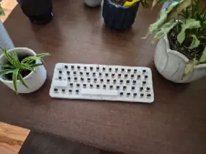
65-key Handwired keyboard - ANSI
Printables

Check out the full build video on YouTube!
IMPORTANT TO KNOW : This project WILL require customization from YOU to adjust the design for the specific keyboard layout in your country. You will be required to modify both the keycap files, and the firmware in order to make this work. You will also be required to make small modifications to a microcontroller (soldering) in order to make this project work, so some technical experience is recommended. I've tried my best to make understandable instructions for all of this but can't guarantee they're easy to follow for everyone. Attempt to build at your own risk.
Print volume required 300x300mm, but the .step file is included so it’s possible to modify the model to be split into smaller parts. If you do make a split version work, feel free to post a remix!
Parts required for this build: 65x MX style Keyboard switches 65x 1N4148 Diodes Some wires (random leftover wires will work fine). Arduino Pro Micro (Microcontroller) 12x M3 threaded inserts (OD4.6mm) 12x M3x10mm screws 1x Heavy duty paper clip (Or metal rod between 1.5 and 2mm diameter)
Tools required for this project: Soldering iron Wire cutters/filament cutters Screwdriver OPTIONAL: Some grease for the stabilizers.
Recommended print settings: Material: PLA Nozzle: < 0.4mm Layer height: < 0.1mm (especially for the main body and stabilizers) Supports: NO (custom supports are built in, remove with pliers after print)
ASSEMBLY
It’s recommended to read these instructions in combination with the build video on YouTube for the best overall understanding of the build process.
- Start by printing out the main body and the keycaps. Remove the custom supports on the main body using some pliers. (Remove red parts).
- Print out the stabilizer kit.
- Add M3 threaded inserts to 10 holes on the bottom, and 2 holes from the front of the chassis. Insert OD: 4.6mm.
Add ten inserts from the underside like this.
And these two from the other side (top).
- Push in place stabilizer gliders into the SPACEBAR, BACKSPACE, ENTER and CAPS LOCK keys. Keep in mind that the little stopper on the glider must be facing towards the switch. (See picture below)
The gliders are marked with a tiny arrow that should be on the side of the pivot bar, and also face in towards the switch. If you look closely, the hole for the pivot bar is slightly angled, this is angled down towards the pivot bar groove to follow the natural angle of the pivot bar.
- Carefully snap into place three short plastic stabilizer bars into the main chassis for the BACKSPACE, ENTER and CAPS LOCK.
If the pivoting stabilizer bars move a little slow, you can use fine grit sandpaper to smooth out the stabilizer bar and/or apply some grease to help create a smooth pivoting movement.
Inside the green rectangle we can see some tiny notches that hold the stabilizer bar in place, this is why it’s recommended to use a nozzle no bigger than 0.4mm, and a 0.1mm layer height as these notches are very tiny.
- For the SPACE, BACKSPACE, ENTER and CAPS LOCK keys, push in place the stabilizer gliders in the two “plus” shaped holes on each side. Make sure the little flap on one side of the glider is facing in towards the middle.
- Push in place the mechanical switches of your choice into the BACKSPACE, ENTER and CAPS LOCK positions. There’s a little hole in the switch that should face towards the stabilizer pivot bar.
- Grab the keycap and ensure that the stabilizer bar is threaded through the holes in the glider pins before carefully working the switch into place. Repeat for all three switches.
- Grab a heavy-duty paperclip, or metal rod up to 2mm diameter. Bend into one long straight rod.
- Add a sharp 90-degree bend to one side. Use the 90 degree bend as a reference on one side to know roughly where to make the opposite 90 degree bend. Adjust if necessary so both bends are as close to the center of each glider pin slot as possible.
- Cut the metal rod so that it sits barely inside the edge of the glider pin slot.
- Add the two metal rod clamps and secure them in place using two M3x10mm screws.
- Add the mechanical keyboard switch for the SPACEBAR, make sure this one has the little hole facing towards you.
- Take the SPACEBAR keycap with the glider pins installed and orient it the correct way before carefully threading both sides of the metal rod into the holes in the glider pins, then work the spacebar into place. OPTIONAL: Add grease to the glider pins and stabilizer metal bar for smoother operation.
- Install all the remaining mechanical key switches with the little hole facing towards you.
- Install all the remaining keycaps. Keep in mind that the key mount is rectangular and will only fit one way.
WIRING
- Take a look at the wiring diagram shown here, this is how we want our wiring to look. The wiring is separated into horizontal rows and vertical columns. (See attached video for explanation)
- Grab 65 pcs 1N4148 diodes. A diode is an electrical component allowing a current to flow one way, but is blocked in the other direction allowing for a one-way signal. There’s a small black mark on the 1N4148 diode indicating the direction of electrical flow. This black mark MUST face away from our switches.
- Cut the RED side of the diode down to about 5-7 millimeters and bend the BLACK side of the diode 90 degrees. Do this for all 65 diodes.
IMPORTANT: Make sure to place the diodes so the electrical flow faces away from the switch, not into the switch. The little black mark on the diode marks which side the signal flows out of, and this black mark MUST be facing away from the switch pin.
- Each diode connects to the upper left pin on the switch. The next diode connects the exact same way to the next switch, and the next diode to the next switch the same all the way across the row from left to right. (See pictures and attached video for further explanation)
- When one row is complete, join all the diodes together. Make sure to join them AFTER the black mark.
This way we get a row that all the switches can send a one-way signal into, but no signal can go back through any of the switches allowing us to isolate the signal from each switch individually.
- Do the exact same for the remaining 4 rows. If necessary, add short cable extensions to the diodes around the spacebar if the diodes are too short to reach all the way.
PRO TIP: Before moving on, take a couple minutes to inspect the soldering of every single diode to ensure that it’s all connected properly in the correct orientation. Potential mistakes will be much more difficult to troubleshoot once the rest of the wires are connected.
- Look at the wiring diagram once more.



Names are used only to indicate the source of a result. Polyzon is not affiliated with the listed sites.