
Free 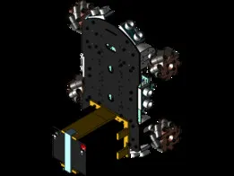
Mecanum gCode Car
GrabCAD


Basic idea
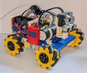
A circular structure covers a 4 wheel car chassis with Mecanum wheels. The Mecanum wheels enable the plate to move in any direction.
When the plate is pushed from any side, a sensor measures the direction of the push. The direction is translated to commands to the four Mecanum wheels, which will move the whole thing to that direction.
The robot is connected to the Arduino Cloud, which enables remote control using a smartphone.
Videos
Without further ado, here's something to look at.
This is Snootybug in modest action. I don't want to scare Tessa with a fully responsive and noisy Snootybug. She needs to gain trust. First she learns that Snootybug can give treats. Then she learns that Snootybug can move.
Concepts explored in this project
- Mecanum wheels - Multicolour print of 2D graphics with a single extruder 3D printer - TLI493D magnet sensor - Creating objects larger than the printer bed - Analog 3D printing Hardware and software used
- Prusa MK3S+ printer and Prusa Slicer - Tinkercad for designing everything - A robot car chassis with Mecanum wheels from Hiwonder - TLI493D magnetic sensor from Infineon - Arduino MKR1010 board - 2 * L9110S drivers for DC motors - Hobby servo motor - Hot glue gun - Arduino Cloud Example of use
1:
The robot car is set to travel 30 cm at each push. The task for your dog is to nod the robot to move to a marked spot on the flor. When the robot reaches the spot, you push a button on the remote and the robot gives a treat to your dog.
2:
The robot performs a similar task, but now it moves without stop. At each nod or a hit against a wall or furniture, it changes direction. You can always make it stop using the remote.
3:
Just control the movement of the robot using your phone as a remote, teaching your dog to play with it and make your dog bond with the robot using the remote controlled treat dispenser. Come up with new tricks and stunts on the fly.
The structure
A robot car chassis with Mecanum wheels is used.
The chassis is covered with a 3D printed cylindrical object, which hides the wheels. I refer to this part as the bottom plate. Some electronics is attached to the chassis, some to the bottom plate. The bottom plate will also include the treat dispenser.
The top plate lies on top of the bottom plate. With the help of six special designed “plate bearings”, the top plate can slide in any direction, some 14 mm.
In the video, I have three of all 6 plate bearings in place and the sliding works perfectly already. The final design has three more bearings to add stability. I'll also add rubber strings to make the top plate return to its central position after a push.
Roller plate bearings
- The top part is a 3D printed, 1 mm thick plate. Its top layer is a bit rough, as 3D prints tend to be, perfect for being glued onto the bottom surface of the top plate. The bottom layer of the top part, being printed against the printer bed, is very smooth and perfect to roll over the 10 mm steel ball. - A ring is glued onto the top part. Together they form the top bed of the bearing. - The bottom part is printed in one part. It is glued onto the bottom plate of the robot. It has a small, slightly concave middle area, while the rest of the bed has a curved edge with a 5 mm radius curvature. The ball is free to roll 7 mm from side to side in any direction. The top plate can hence slide back and forth 14 mm in any direction. The plate bearing in action.
The sensor
The idea is to read how much the top plate has been pushed and in what direction. For this I use Infineon's TLI493D sensor. More specifically, the 3Dsense Shield2Go board. It will be placed on the bottom plate with the sensor element at the center hub. A magnet is attached to the top plate. The sensor gives exact information about how the magnet moves above the center of the hub.
The remote
The dashboard for the robot has pushbuttons for moving in 8 directions, and a stop button. Each push on the button adds a velocity unit in that direction. Full speed requires about 10 pushes. Any push extending the max speed will result in truncating to the max speed.
Three switches work like radio buttons, turning each other off when activated. They define in which mode the robot operates:
- Continuous movement. When pushed (by the dog), the robot starts moving and changes direction if it collides at something or is being pushed again. It only stops when the Stop button is pushed. - Timed movement. The robot moves 1 to 10 seconds and stops after that. During that time it might change direction if colliding or being pushed again. A push while movement won't restart the timer. - Phone controlled. The robot movements are controlled only with the phone. The Treat function is active all the time. Pushing it will make the treat slider move back and forth once. The speed slide sets the maximal speed of the robot. The time slide sets the time the robot moves at each push, when in Timed movement mode.
The bottom plate
The bottom plate seen from below. It needs to be cut in two in Slicer to fit on the printer bed. Four poles with hexagonal holes fit perfectly to the robot car chassis. The hole in the middle enables the magnetic sensor to stick up and reach a magnet attached to the top plate.
The treat dispenser
A small funnel is situated in the bottom plate and filled with treats. The bottom of the funnel drops a treat or two into a cylindrical cavity of a slider. The slider lies on top of a stopper plate. When the slider moves sideways with the force from a servo motor, a part of the slider blocks the bottom hole of the funnel while the cylindrical cavity sticks out from the side of the bottom plate and drops the treats on the floor. The slider slides back and a new treat falls into the cylindrical cavity. This mechanism is activated by a push on a button on the phone.
The treat dispenser viewed from underneath.
a) is the funnel, which will be filled with treats. b) is the slider, rotated by the servo (d). c) is a plate preventing the treats from falling on the floor, when the hole in the slider is in line with the funnel hole. e) is the opening for the slider to slide out.
The artwork. How to do graphics with a single extruder 3D printer.
I used Pinta to draw the following sketch:
This is made in Pinta, but any pixel based graphic editor will do (Paint.net, Gimp…). I read this image into Inkscape and did a Trace Bitmap. I got this:
To the left I have the pixel image from Pinta. To the right I have the traced bitmap. I used the following settings in Inkscape, when tracing the bitmap:
The essential settings are:



Names are used only to indicate the source of a result. Polyzon is not affiliated with the listed sites.