
Free 
Automatic Microchip Pet Feeder
Thingiverse


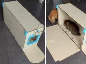
Purrmission Feeder - a microchip cat feeder that opens (gives permission) only to the registered cat. No more greedy siblings stealing your cat's food!
Introduction
The Purrmission Feeder is the answer to the age-old problem. You have a greedy, chonky cat and a scrawny shy cat, and the shy cat can't seem to get its correct portion without overfeeding the chonky cat, or by physically guarding the cats while eating.
There are a few microchip feeders already available commercially, but they are all pretty expensive, and the cost for the problem's solution skyrockets when you have more than two cats. This is my main reason for doing this project: my parents have 4 cats, and one of them has 10kg, is sized like a small dog and won't stop bullying the rest of the cats for their food. De-chonking that cat is also difficult, since he needs to eat diet food (either he eats the other cats' food, which is tastier, or all eat diet food, and the shy cats lose even more weight which they don't need to lose).
So, my solution aims to be as easy as I can make it: easy to build, easy to assemble, easy to service and easy to change it to however you want (maybe even for dogs or other pets). This is why the design is fully modular, uses common Arduino components and the parts are small enough to be printed on smaller printers (like mine, a Prusa Mini)
Functions
- Fully motorized flap that blocks or reveals the food bowl - RFID reader mounted at the front of the feeder - A side-mounted button to register or delete accepted RFID tags, preventing accidental cat-presses - Cable channels on the side and ample space in the back for all the electronics. These spaces are oversized so that even people who don't know how to 3D model can improve the electronics
Limitations and future plans
Due to poor planning on my part, the RFID reader I used cannot read pet microchips, because ordering a compatible one would've taken longer than I can afford. In theory, a microchip compatible reader can be used without too many modifications, but I didn't test the code or the range for it.
Some design parts are rushed, because I finished this project a few minutes before the competition entries ended. I encourage feedback and questions, and I will do my best to fix some of the inevitable mistakes I made. The servo mechanics are finicky, I will smooth them out soon (after I get a few full nights of sleep)
A design part that is most certainly rushed is the "main body" part, the one where the food bowl resides. I wish I would've planned for it to be more printer friendly (or more Prusa Mini / small beds friendly).
Most of my mistakes come from the fact that I never designed anything this big, and certainly not for anyone else, so the 3mf files are a bit of a mess, but I still hope they can be useful.
Future plans
- Add microchip support - Design a circular antenna (like other microchip feeder) for a wider area of reading - Sensing if the servo encounters difficulties (like a cat head that won't back down). Again, in theory it should work with any servo, but I didn't have the time to test it - Fixing the flaps to the servo, so that closing isn't slamming - Designing a cover addon so that greedy cats can't steal food sideways Hardware and software used
Hardware
- Arduino (Uno, but others should be fine) - RFID Reader - mine is RC522. It came in a kit and I've seen it everywhere on websites, so it should be one of the most common - RFID tags * (one for each cat that should have access) - In theory, any tag should work. You should match the frequency of the tag to the frequency of the reader. RC522 is a 13.56Mhz reader, so I got 13.56Mhz tags - Servo motor - SG90. Again, it came in a kit - A button - Two LEDs - the code is written for them, I will include them in the wiring diagram, but I ran out of time to include the holes for them * - Each tag has an identifier (UID). In some cases, buying a "set" of them gives you tags with identical UIDs (if they are writable, you can overwrite it using the same RFID reader - at least RC522 can). This should not matter in a scenario with two cats, but if each cat has its own feeder, they could get mixed up.
Software
- Arduino IDE for the Arduino code - Fusion 360 for the modelling
Wiring diagram
Code
The code scans constantly for a new RFID tag. If it finds it, it checks the internal list of saved tags (10 tags, it stores the UID of the tag). If the tag is saved, it opens the servo. If the tag was not saved, it lights up a red LED.
The servo is programmed to close automatically after 5 seconds after not detecting a valid tag. If a valid tag is kept on the reader, it will know it and keep resetting the timer (so if a valid tag is left on the reader, the servo will never close)
This behavior is easier achieved with controlling the servo as a state machine (the ServoState enum), so that I can always know what the servo is doing. Also, the state machine helps with making the servo move slowly while keeping the main thread free for scanning at the same time.
The button has two functions: single press for register, double press for delete. The button functions will "act" on the last scanned tag, so to register a new tag, you first scan it, then press the button (same for deleting it).
The button also has a thing called "debouncing": if you just plug in a button and press it, it will sometimes generate a few consecutive presses in a tiny amount of time. Debouncing just accounts for that behavior.
Printing Instructions
The design features the following parts: - Main body - the square that holds the food bowl - Cable channels - two, mirrored, so each is unique - Front body - the area where the RFID reader is situated - Flaps - two, again different. The back flap has longer side pins. When closed, they have a slight inward curve, so they cannot be raised by a cat pushing the front - Rails - the guides on which the flaps slide - Electronics box - a big compartment in the back for the servo, button and Arduino. It has a big hole for the button, and a small hole for the Arduino cable. The top can easily detach, with magnets. - Servo wheel - a circle-like shape that helps the servo push the flaps in both directions (up - open, down - closed)
Most of the parts should be printable without supports. The tricky parts are the front body (because of the RFID mount), the main body (because it's huge and weirdly shaped) and the electronics box, because of the magnet mounts. The STLs are as-exported from Fusion360, you’ll need to orient them for printing.
I printed them all using my Prusa Mini. I sadly cannot give accurate estimates for material or time or print files, because I use a weird filament and a 0.6 nozzle (which is not the norm from what I've seen)
For the main body, I split it in half (top and bottom), and the top I printed upside down, with supports for the filleted circle for the bowl. The electronics box lid I split again, because it needs supports for the magnet holes, and with the supports, it can't fit on a Mini's bed. As for the front part, I printed it on its narrow edge (with the walls going up), and supports for the RFID mount (my supports decided to quit their job, so that's why the front part is so scuffed in the pictures)
Assembly Instructions
The parts are assembled by clipping the dovetails to eachother. The tolerances are snug for me, but print a test dovetail piece (one male tail and one female socket) to make sure they're a snug fit. I didn't need to use superglue, but it's okay if you want it.
If you want to use superglue, try assembling it all before gluing. Some steps require trial and error, assembling and disassembling.
First, put the RFID reader in its mount. My mount design is made for a RC522 held in place with a strip of cable management velcro (because it has a big component on the front, it won't stay flush).
Then, clip the front part on the main body. Route the cables you need and clip on the cable channels.
The bowl insert is made for an IKEA pet bowl (Lurvig stainless steel bowl, somehow I can't find it anymore on their website). If you are using a different bowl, or just want to make sure, this is how you test the flaps: - put the pet bowl in - clip on one rail - arrange the flaps assembly (one long pin in the rail hole, the hinge should be facing the bowl) - clip on the second rail - test if the flaps path is clear (it shouldn't snag on the bowl, and when closed should cover the whole bowl and cave a little, so it can't be pushed open from the front)
Clip on the rails and flaps like instructed above (one rail, arrange the flaps, second rail)
Before continuing, you should test to see if the servo functions correctly. If using SG90 and the same attachment as I used, the servo should slide in the slot in the back of the main body piece. Upload the Arduino code and plug it in (so that it runs the setup function once). This resets the servo to the starting position, so that you can accurately put the circle piece. You should also test using the flaps. If the servo is not positioned correctly, it won't have enough force to lift them.
Then, just the finishing touches remain: the electronics box. Glue in the magnets, clip in the bottom part and arrange your stuff. The box features a big button-sized cutout and a small cutout for the USB cable. Then, if everything is tucked in, clip in the lid and it's done!
Usage instructions



Names are used only to indicate the source of a result. Polyzon is not affiliated with the listed sites.