
Free 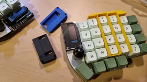
Aurora Lily58 Oled Housing
Printables


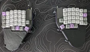
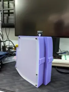
A case and plate for a handwired Lily58 split keyboard. Here is the GitHub repo from the original design.
I built my version using a RP2040 Pro Micro. For interconnect I used DuPont connectors because they are very easy to find and they don't short when unplugged as TRRS does. To avoid plugging it in backwards I used this model to block one of the middle pins. This will stop you from fully plugging it in but they may still be able to touch the contacts so I recommend that you still unplug the keyboard when connecting the sides (plus sometimes the sides won't connect properly).
Parts:
- 2x RP2040 Pro Micro ( link ) - 68x 1n4148 diodes ( link ) - 68x MX Key Switches (I used Akko Lavender Purples) ( link [this has 45 switches per box]) - 68x MX Keycaps (66 1u keycaps and 2 1.5u keycaps) (Joe Scotto's ScottoCaps are good if you want printed ones) - Bare solid copper wire - Heatshrink (to insulate the solid wire at intersections) ( link ) - Stranded wire (to connect to the mcu. I used the wire from an ethernet cable) - 10x m2 x 8mm standoffs ( link I used these from amazon but there are much cheaper ones from AliExpress) - 20x m2 x 6mm bolts
(If you will crimp the connectors yourself, you need these, otherwise you can use pre-made DuPont cables and cut and solder wire to extend them. My interconnect cable is 1m long)
- 4x 4 pin DuPont housings - 6x Male DuPont crimp pins - 6x Female DuPont crimp pins - (I have this kit of crimping supplies) - Wire for the cable – I used a short ethernet cable and cut of the connectors
After printing the case and plate, you will need to cut through the sacrificial bridging in the screw holes with a knife.
Wiring:
The columns are connected to: GP27, GP26, GP22, GP20, GP23, and GP21 from the outside to inside. (The sides are mirrored of each other.)
The rows are connected to GP5, GP6, GP7, GP8, and GP9 from the top row to the bottom.
The interconnect is connected to GP1, GND, and +5v.
I highly recommend this video for the actual wiring of the board and explanation of how things work.
For the interconnect, I used the female side of the connector in the case and had the male side in the cable. The connectors are simply hot glued into place in the keyboard.
Firmware:
I modified the default Lily58 firmware which is included in the QMK repo ( link ) to make some changes (I use a different keymap [colemak] and added some extra keys like volume, pause/play, media next, media previous), but you should be able to use the original and just change the pins, set the processor and bootloader to the RP2040, and disable all of the extra features (screen, LEDs, etc.).
You can also just use KMK POG which will also let you set up the keyboard graphically.






Names are used only to indicate the source of a result. Polyzon is not affiliated with the listed sites.
Comments