
Free 
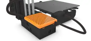
Prusa MINI+ extruder with filament sensor
Printables
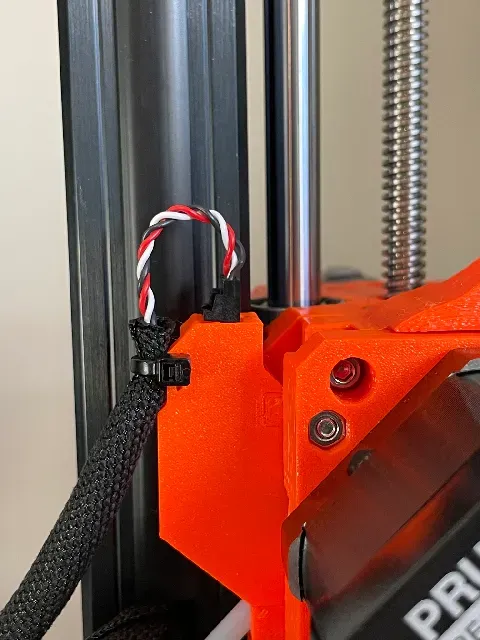


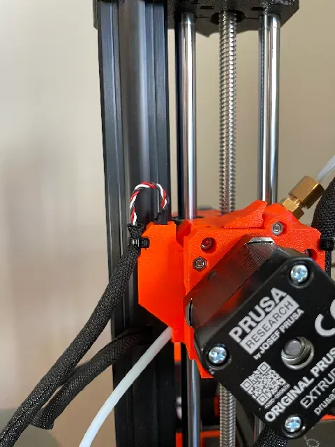

This is a modified Futaba J connector mount for the Prusa Mini extruder filament sensor modification designed by Czech Maker . The changes are:
- Click-in socket for the Futaba J connector from the Prusa Filament Sensor - Socket is keyed so it is not possible to install the connector in the wrong orientation - Mounting point for zip-tie to hold the Filament Sensor cable for strain relief This should be compatible with both the Futaba J connector with a locking clip and directional key (like the one that comes on the Prusa Filament Sensor) and standard Futaba J connectors.
Print Settings:
Material: PETG Layer height: 0.15mm Quality Infill: 100% rectilinear Supports: Not recommended
Assembly
Follow the steps in the Prusa Mini extruder filament sensor assembly, but use the modified rear cover in this remix instead of the standard one. Before installing the rear cover, check the fitment of the connector into the socket and make sure it inserts and removes easily. See Important Notes section below for some tips on this. This is also a good time to test the sensor is working, before the extruder is fully reassembled - plug the connector in and use a piece of filament to make sure that the Prusa Mini recognises when a filament is inserted.
Once the extruder is fully reassembled onto the Prusa Mini, plug in the filament sensor cable and secure it in place with a zip tie, using the mounting point.
Check again that the sensor is working correctly. If not, first check Settings > Filament Sensor is set to “ON”. I found at one point during testing of my part and multiple connections / disconnections, my Prusa Mini had changed this setting to “OFF” on its own.
If the filament sensor still isn't working, check that the levers for the optical sensor blocker are moving freely and that the beam blocker is centered properly in the optical sensor. You may need to loosen the M2 screw holding down the circuit board and position it so that the beam blocker is exactly in the middle, before re-tightening the M2 screw.
Important Notes
- There is a small amount of bridging inside the socket that the printer needs to handle to print this part, as it's not possible to orientate it on the print bed to avoid it. - I have not tried to print this with supports. Given the small size of the socket, I think removal of supports will be more trouble than its worth. - The design tolerances are fairly tight for the socket where the connector plugs in. If your printer is set up to handle bridges well, the connector should push in easily, without force. If not, you may need to clean up any saggy bridges. - If it doesn't push in easily, do not force the connector into the socket as it may be difficult to get out. Remove the connector from the socket and use a small file or knife to tidy up any sagged bridges - If you have forced the connector into the socket and are having trouble getting it out, do not pull on the wires to remove it as they may be damaged. Remove the connector back plate from the extruder and push the connector out from the inside, using a small, blunt tool. Full credit for the original design of the combined extruder filament sensor goes to Czech Maker , in my opinion his design is much better and neater that using the external filament sensor - I think this is a mod all Prusa Mini owners should make.


Names are used only to indicate the source of a result. Polyzon is not affiliated with the listed sites.