
Free 
Generic ESPHome / electronics enclousure with JST plug (parametric)
Printables
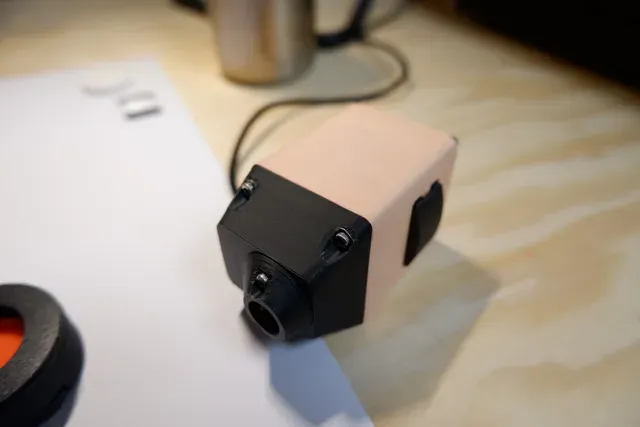


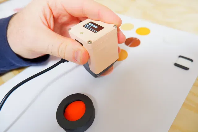
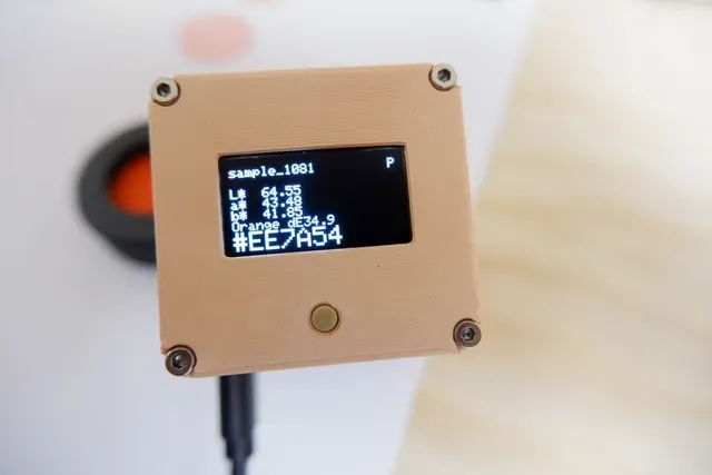


This is a DIY colorimeter, a device that can be used to recognize the color of a thing, wall paint, paintings, textiles, 3D-printing filament (swatches) and many more things. It is the kind of device that was mentioned in Prusas blog post about full spectrum printing and typically cost ~200€ for a cheap one, more like 2000€ for a professional one. I used mine a lot to analyze natural dyes and using them on 3D-printed objects (using the spectral data the device offers, too).
How it works
Very simply put: The device shines a bright light onto a surface at an angle and analyzes the light that gets scattered off it with a spectral sensor. That is compared to what a "white" reference sample looks like and is used to approximate a rough spectrum and calculate the color a human eye would see.
Why shine at an angle? So we don't just measure the light reflected off it. Reflected light (input angle ~ output angle) mostly has the spectrum (and therefore color) of the light source. Explicitly looking from another angle gives us only the true body color of the sampled surface.
Why compare against a white reference? This eliminates the unknown spectrum of the light source, the complicated influences the devices geometry has on the illumination and the unknown sensitivity of the sensor itself (mostly). More on the sensor later.
Why use a spectral sensor and not an RGB sensor instead? RGB only covers a small area ("gamut") of the visible light. Looking at multiple points of the spectrum instead of just 3 allows us to cover a wider area.
Instead of RGB, the device uses the CieLab color space as output. The L*, a* and b* coordinates are non-linearly scaled to represent the color perception of the human eye. Equal distances in either coordinate should register as an equal difference in perceived color. RBG is displayed, too, wherever that's possible.
The sensor
The main component of the device is the Adafruit AS7341, a digital 8-channel spectrometer board. It uses narrow band spectral filters on 8 individual photodiodes to measure different components of visible light. On top of that comes a measurement in the near infrared (NIR), plus an unfiltered one (clear). From these 10 channels the visible spectrum of the incoming light can be roughly interpolated. It is good enough for smooth spectra, but can be off for "spikey" spectra that fall outside the narrow measurement bands.
The light source
In order to see light scattered at every visible wavelength, we need a smooth light source that gives a sufficient amount of light over the entire visible spectrum. This device uses a Nichia Optisolis LED which is rated at 95 CRI and comes extremely close to the spectrum of black body radiation at 3000K (warm white). It actually doesn't matter which LED is used exactly, as the device only cares about the difference between the light coming off a white sample and that of the actual sample, both reduced by what the sensor sees from an ideal black (dark) sample, the reflectance . But a single Optisolis is not that expensive (1€) to justify using something less.
Other components
The device uses a Waveshare ESP32-C3 Zero to read the data off the spectrometer, react to the user pressing buttons, calculating and storing the results. It also has BLE to transfer the data to a smartphone. A 0.96" SSD1306 oled display (which are dirt cheap) is used to display stuff to the user. An optional (but strongly recommended) 700nm NIR filter (anything between 4.5mm to 10mm round or rectangular will do, at most 1mm thick) reduces the amount of NIR light that is messing with the other channels. Polarization filter plastic foil (a few € for an A4 sheet, enough to outfit 100s of such colorimeters) can help further reduce specular light from very glossy samples that will reflect in all sorts of directions.
Additional utilities
A beam trap is necessary to verify you don't get any internal reflections in your device and to quantify the spectrometer noise. I used an IKEA ENKELSPARIG stainless steel bottle, some black fabric and a printed adapter that reduces the opening to 22.5mm. I consistently read all zeros on the "dark" measurement, which means the beam trap works perfectly, the geometry of the measurement tip is good at not reflecting light back at the sensor itself, and the sensor is not seeing any ghosts.
You need a good white reference. If you can get some cheap spectralon online that is the preferred solution, but some flat wound PTFE tape does also work, so long as you use polarization filters: It's glossy, and way more perpendicularly than parallelly.
Limitations by design
The device has no battery and needs an external USB power source (powerpack, plug, mobile phone, computer...) to work. Working with batteries (especially LiPos) is tricky and introduces security concerns. It also makes it harder to connect the device via USB (e.g. to flash new software to it or transfer data) because of multiple voltage sources present.
Right now this has another consequence: This version does not yet feature a constant current sink. Different USB power sources have slightly different voltages and will drive the LED differently. If have a series of plans to improve on this, but for now that means that you need to do a white reference measurement whenever you change your power supply. It's not a big inconvenience, as you should do that anyways whenever you start a measurement series and - ideally - a few times in between, to be able to counter voltage drift or changes in internal temperature of the device.
Building one
If you are interested in building one of these for yourself, be advised that this requires more than just accurately printing some parts. You'll need to
- Assemble quite a few components and post-process them if there are printing artifacts
- Put in lots of tiny M2 heat-set inserts, a few in a little difficult position (at least in the current version)
- Solder wires to breakout-boards
- Solder half a dozen JST-PH sockets and 3 smaller electrical components to a tiny 6x10 perfboard and connect them with each other. (This will get a lot easier once I get around to designing a proper PCB board one can just order)
- Flash an ESP32 with some firmware (which I have already written).
Generally: The current device is a (well usable) prototype. You should expect some less-than-perfectly documented assembly steps and some details I will gloss over in the instructions. Please let me know if anything needs clarification, something is completely missing or something seems stupid (it's well possible that it is). Writing documentation and instructions is hard. Expect some tinkering. The current design is just the latest state of an iterative design process, with some of the features no longer in use. Some earlier design decisions have come into conflict with later improvements. I have a long list of things I need to work over, but I wanted to document the current state and put the device "as is" out there. I plan to make further improvements to it, that will probably gradually update every piece of the device over time.
Tools & consumable materials
- 3D printer (duh)
- soldering iron, solder, soldering equipment, blank wire, coated wire (helpful)
- heat set insert tip for soldering iron (optional, but recommended)
- soldering paste (for attaching the SMD LED onto the star PCB, but it can be done without)
- cutting plotter (only if you want to have polarization filters, optional)
- multimeter (for finding shorts and the like)
- breakout board (in case you want to test things before everything comes together)
- wire stripper
- tweezers
- screwdriver matching the M2 cap screws you use
- a USB-C cable that supports data transfer (many USB-charger cables won't do)
BOM



Names are used only to indicate the source of a result. Polyzon is not affiliated with the listed sites.