
Free 
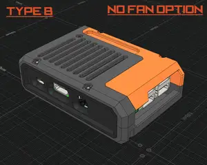
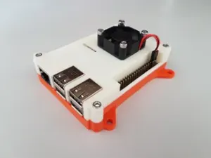
Raspberry Pi 3 (B/B+) case, VESA mount, internal fan
Printables
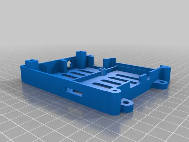


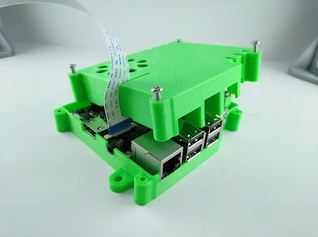

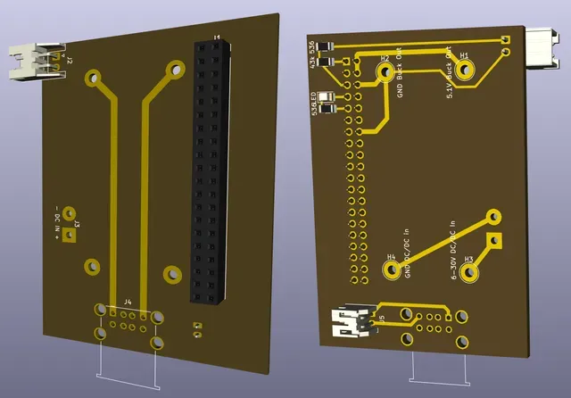
I designed this Raspberry Pi enclosure for my Octoprint server. The Pi receives its 5.1 volts power via the 40-pin connector from a buck-boost converter (XL6009, two coils) that is soldered to the flip side of a 5 x 7 cm single-sided perfboard. The converter also powers directly an extra pair of USB sockets that are only connected to the 5.1 volt rail.
I'm running the Pi from a 120 GB USB SSD drive, which came with a Y cable (split power and data) so this avoids running its supply through the Pi’s mainboard.
The buck-boost converter is able to maintain 5.1 volts output over an input range of 4 - 32 volts with high efficiency. I wouldn’t run it at its (claimed) 4 amps rating though ...
The opening for the Pi camera cable is a slit that extends through the upper shell into a thick guide block that maintains some integrity for the enclosure. You can put the upper shell in place or remove it by sliding the flat cable in or out without unplugging it.
Opposite to the HDMI and audio ports is a 42 x 6 mm slot that fits several JST-XH sockets mounted horizontally. I use it for connecting a shutdown switch and a level-shifted SPI out to drive a 32x8 pixels LED matrix display.
You'll need additional parts:
- a 5x7 cm perfboard (i prefer single-side pertinax because one side without copper is good for creating wire bridges) with a mounting hole spacing of 40x64 mm
- a socket for a 12 volts plug / barrel jack, usually 5.1 mm Ø with a 2 mm pin
- any regulator that fits under the perfboard and can be set to output 5.1 volts stable
- a USB twin socket
- a 20 x 2 pin Pi connector
- a 40 x 40 mm x 10 mm 12 V, 100 mA fan (or 5 V for maximum noise ...)
- a connector for the fan, (or just the willingness to solder its wires to 5 volts somewhere on the perfboard)
- 4 pcs. M3 x 25 screws for the enclosure (or 4 pcs. M3 x 15-20 for the upper2.stl variant)
- 2-4 pcs. M3 x 8-10 mm screws for the fan (some fans can be press-fit without screws)
- 4 pcs. M3 x 6 mm screws for the Pi
- 2 pcs. M3 x 6 - 10 mm screws for the perfboard
Print Settings
Printer:
TronXY X5S
Rafts: Doesn't Matter
Supports:
No
Resolution: 0.6 mm nozzle, 0.28 mm layer height
Infill:
15%
Filament:
Generic budget PLA any Post-Printing =============
CHECK THE VOLTAGE OF THE BUCK CONVERTER FIRST!
Do not plug things in and fire them up, because you may end up with fried Pi. My converter came pre-dialed to 16 volts, and there's no telling what yours may be set to.
No soldering yet, just checking if things will fit
Step 1: Soldering the power supply
DO NOT START SOLDERING YET. I designed this enclosure around the parts I had at hand. No guarantee that it'll match yours.
Mount the Raspberry Pi and the 12 volts socket to the lower shell, then loosely place the perfboard, the USB socket and the pin connector to make sure they line up with the mount points and enclosure holes. If they do, proceed. Otherwise you'll need to drill, saw or file to make things fit … good luck. Connect the IN+ of the converter to the 12 V + of your supply, and the IN- to the ground.
I used four pins on the IN/OUT solder patches (or pieces of thick wire will do, too) to mount the converter to the perfboard, with 3-4 mm distance between boards.
Connect the OUT+ to the Pi pins 2 and 4 (the outer top pins of the 40-pin connector).
Connect the OUT- to Pi pins 6 and 14 (see picture below; I used wire on the flip side to make the connections).
Connect the OUT+ and OUT- to the USB sockets (see pictures below for connections and polarity)
Do not plug in the Pi yet.
Minimal connections for the power supply. Also requires wires on the flip side.





Names are used only to indicate the source of a result. Polyzon is not affiliated with the listed sites.