
Free 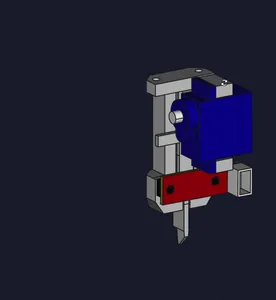
EG's Servo Probe
Printables



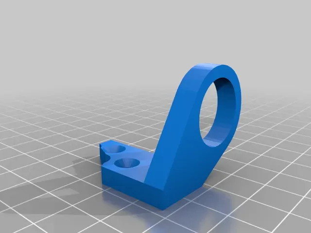

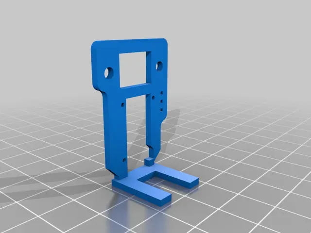
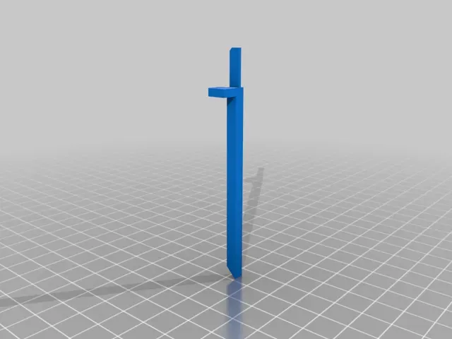


a.k.a Tiny Touch MK3 , a bit more background on why I design this will be available on my blog.
Printed parts:
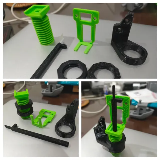
- body: printed on its back, mirror it for left motor. Use a more malleable filament like ABS is recommended, easier to cut threads.
- flag: printed on its back, mirror it for left motor.
- nut: print it twice.
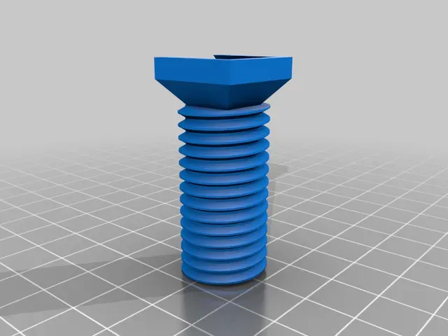
- thread: print it slow, 0.2mm layer height at most. I print mine with 0.16mm.
- mount: optional. I design it for this carrier. But any 18mm sensor mount will work.
Non-printed parts:
- Optical endstop ( Aliexpress )
- Tiny linear servo ( Aliexpress )
- Servo extension cables — 3pin each.
- 3pin JST-XH connectors — 2.54mm pitch. 1 male, 4 females at the minimum, but really, just get a box for less than $10.
- A couple of M3 and tiny screws for smartphone or glasses.
Putting this together should be dead simple. Push on the male JST-XH connector into body (into those 3 tiny 1mm holes), then screw optical endstop on top of the body, servo below it, screw it on from the back. Add tape or sticker to the thin part of the flag to make it more flaggy, then slide in it into the thread square hole. Also slide the body into the top of the thread, the thick nubbin on the flag should rest on the servo arm. Solder the servo wires into the male JST.
Order doesn’t really matter, just align it when crimping the wires. Voltage (red) to board 5V, Ground(black) to board ground, and signal (white or orange) to board signal for each of them. You’re very likely to criss cross some wires because of how the endstop (signal in the middle) is wired against how normally printer board pinout is designed (ground in the middle).
If you don’t have a dedicated servo port on your printer board, like the stock Anet A8 boards, you can splice the power off the optical endstop. Read my complete tiny touch guide for Anet A8 if you need more help on this.
Marlin
#define Z_PROBE_SERVO_NR 0 // Defaults to SERVO 0 connector. #define Z_SERVO_ANGLES { 160, 30 } // Z Servo Deploy and Stow angles
#define NOZZLE_TO_PROBE_OFFSET { 40, -5, 0 } // adjust this accoring to your own mount
#define AUTO_BED_LEVELING_BILINEAR
#define LCD_BED_LEVELING // optional
#define NUM_SERVOS 1
#define SERVO_DELAY { 600 }
#define DEACTIVATE_SERVOS_AFTER_MOVE Compile and upload.
Configuration
- M280 P0 S[angle] ; I use M280 P0 S160 to deploy and M280 P0 S30 to stow.
- M119 ; While doing step 1, confirm the Z endstop status by sending It should return open when deployed, and TRIGGERED when stowed. Please don’t just hit home and hope that things won’t crash into each other.
- M851 Z0 ; Reset the existing Z-offset to zero. It should already at zero if you just flash your firmware, but just to be 100% sure.
- G28 ; Home all, or by clicking on the button.
- G1 X110 Y110 Z0 F1000 ; Move everything to center bottom
- M211 S0 ; Disable software endstop, so you can go below Z0
- Now slowly move the nozzle down until it barely touching the bed (do the paper dance).
- Look at the LCD, and take note of the Z value. For example its -1.2
- M851 Z-1.2 ; Set the Z offset
- M211 S1 ; Enable software endstop
- M500 ; Save settings to EEPROM
- M501 ; Load EEPROM
- M503 ; Confirm settings
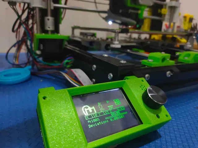
You’re done. Remember to add G29 ; ABL right after auto home G28 in the start gcode in your slicer.
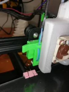
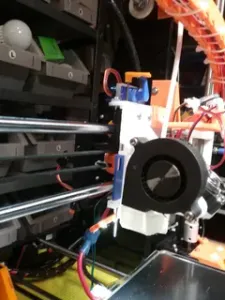
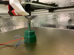
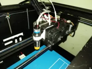
In action:





Names are used only to indicate the source of a result. Polyzon is not affiliated with the listed sites.