
Free 
Microscope adapter for 4x macro photography with Sony A, E/FE, Canon EF/EF-S, RF, M, Nikon F, Z, Fuji X, Leica L, M4/3, M42 cameras
Printables
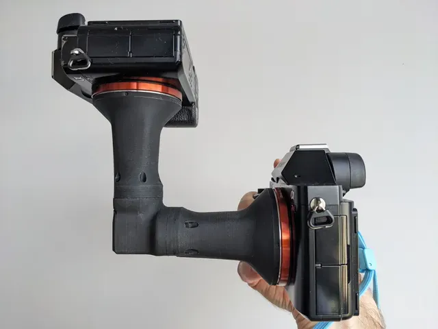






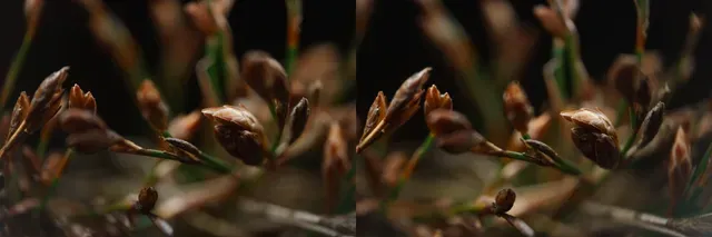

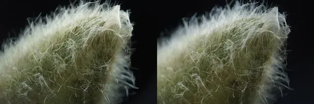
This design combines two 4x microscope lenses together to create a stereoscopic 3D macro lens, with 2x magnification and a 5mm stereo baseline.
It has been designed to be shot handheld in the field using a flash for lighting, rather than in the studio on a tripod, so live subjects in their natural environment can be photographed. Video recording is also possible.
The field of view at the focal plane is 18x12mm on a full-frame camera, or 12x8mm on a 1.5x crop camera. Larger subjects can't be photographed, as the magnification is fixed at 2x.
Two Sony E/FE cameras are required, ideally identical models.
The microscopes shoot through a beamsplitter prism so that one camera can be mounted to the top or bottom of the rig, while the other points towards the subject normally.
The stereo baseline of 5mm is achieved by offsetting both microscopes from the centreline of the prism by 2.5mm.
Each camera is then offset from that position by a further 5mm . This offset is the equivalent of rear-standard shift in a view camera, and causes the field-of-view and focus planes of both cameras to fully coincide.
This approach of shifting the cameras instead of tilting the lenses avoids introducing “toe-in” effects that could make the stereoscopic images hard to view, and ensures that the subject is in-focus from edge to edge from both viewpoints (unlike the problems faced by a Greenough-style 3D microscope).
This is a cross-section as seen from above; the first object is the prism at top, then the offset microscope, then the further-offset camera at the bottom:
I can add support for these mirrorless cameras on request, just leave me a comment if you are planning to build this: Canon RF, Nikon Z, Fujifilm X, Leica L, or Micro Four-Thirds
Introduction to the system
Printing instructions
I have only tested eSUN ABS+ Black filament, and I won't be testing or giving instructions for any others. I would strongly recommend ABS or ASA filament unless you want to experiment with settings and tolerances yourself.
Print one copy of each of these files:
- Full-frame - 5mm baseline - Body set.stl - Full-frame - 5mm baseline - Camera connectors - 2x magnification - Sony FE.stl - 4mm apertures for Reakway 4x microscope.stl With these settings:
- Layer height: 0.1mm - Perimeters: 3 - Infill: 13% rectilinear (or similar) - 9 top layers, 8 bottom layers (or similar) - Nozzle: 0.4mm diameter - Elephant foot compensation (first layer XY compensation): Disable - Filament shrinkage: (required for ABS-like filaments)
- In SuperSlicer set shrinkage to 99.5% in the filament settings - In PrusaSlicer select the models on the buildplate and set the scale factor for X and Y to 100.5%, but keep Z fixed at 100% (unlock the aspect ratio padlock first to allow this). - Perimeter generator: Classic (I did not test Arachne and I've had trouble with it in the past) - Supports: None - Filament: eSUN ABS+ Black. Filament must be black. This specific filament is also very matte, which is optically fantastic. - Fan speed: I used: - 30% constant fan speed for the camera connectors (which is my default setting) - 60% fan speed for the body set (for better overhangs near the bed) - 100% fan speed for the 4mm apertures - … but best settings will depend on your printer and your chamber temperature Print one copy of the “diffuser”:
- White filament, I used white PETG - 100% infill - 0.2mm layer height. Parts and tools
These parts are required:
- Reakway 4x plan microscope objective x 2 pieces. This specific model is required, no lookalikes, as some have wildly-different internal constructions. See pictures below for which internals are the correct ones. - 18mm cube beamsplitter prism x 1 piece - M2x6mm cap head screw x 18 pieces - M2 heatset threaded insert , 3.5mm diameter, 3mm length x 18 pieces - Thin (≤1mm) adhesive black foam sheet (optional) These tools are required:
- Soldering iron with conical tip - Hammer - Chopstick, or similar wooden rod - 1.5mm ball-headed hex wrench (Allen key) - Lens cleaning cloth/microfibre cloth or cotton buds - Lens cleaning fluid or isopropyl alcohol For use with this camera equipment:
- 2x Sony E/FE mirrorless cameras (ideally identical models). Crop and full-frame models are both compatible. - Twin-head snake-arm macro flash (recommended) Assembly
Microscopes
Prepare the two microscopes by unscrewing the silver outer case (right) from the objectives, and discard them:
Note that the internal and external threads on this microscope are too sharp to be gripped with bare fingers without cutting your skin, so use a kitchen rubber glove to protect your fingers! They will also cut through cotton t-shirts.
Unscrew the black aperture disk (right) from the rear of the objectives. Your rubber glove can help you get enough grip to start untwisting this (but don't hold the objective by its silver threads while you do that, because those are sharp too). Screw in the 3D-printed 4mm apertures in their place.
If you have black adhesive foam, you can use it to cover up the shiny silver ring on the tip of the microscope, so that its reflection doesn't get seen by the prism. I used two wad punches to cut it into the correct donut shape. 0.5mm of space has been allocated for this, and my 1mm adhesive foam successfully compressed to this thickness.
You could probably paint it black instead, or just leave it virgin, with some loss of contrast.
Main body heatsets
Use your soldering iron to install heat-sets in the indicated positions only (the 4 brass coloured inserts shown below, not the other holes). I set my iron to the same temperature that I extrude my filament at:
Repeat that on the bottom side too:
Install the 5 inserts shown into both copes of this lens mount piece, then screw a screw into each one of them to push out any excess melted plastic from the rear. Then remove the screws and cut off those excess plastic dags:
Installing the prism
The prism has 3 transparent sides and 3 opaque black-painted sides. The transparent sides will face the microscopes and the outside world, while the black-painted ones will rest against plastic.
If you wear cotton gloves while handling the prism you can avoid putting fingerprints on it, which makes cleanup much easier.
Push the prism (red object in the cross-section below) into the square channel of the main body from the rear, so that its split line is oriented like so, to send half of the light to one camera and half to the other:
You can stick your finger in through the bottom hole to help lift and align the prism (it will be better guided in if it is pressed upwards, in the image shown above).
This prism is retained and aligned by being squeezed by the print itself (see where the channel narrows in the diagram above, near the front aperture of the main body), so it needs some “mechanical persuasion” to be installed.
I stuffed a microfibre cloth into the square installation hole to protect the prism's surface, and then used a wooden stick as a punch with my hammer to hammer the prism home. Verify that the prism sits flush with the front aperture all the way around.
Clean up any exposed faces of the prism with a lens/microfibre cloth or cotton-bud, dampened with lens cleaning solution or isopropyl alcohol. Avoid spraying the cleaner into the assembly directly, because droplets can get trapped somewhere unwanted and leave behind residue when they evaporate.




Names are used only to indicate the source of a result. Polyzon is not affiliated with the listed sites.