
Free 
Relocate Filament Runout Sensor
Printables



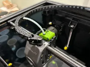
This filament sensor has many advantages :
- It facilitate the filament change operations. When filament is detected by the sensor that triggers an auto load material function. - Since we don't use the rear filament sensor, the reverse bowden path is simplified. This allows an easier insertion of the filament and reduce drag. - It's easier to relocate the spool anywhere you want, it's especially true for the K1. - The sensor works with TPU even if the reverse bowden is bypassed. - It also reduce the length of leftover when a spool ends as the sensor is super close to the extruder. - And it's useful to have a filament runout sensor inside the toolhead when you want to use a MMU (near futur proof ^^ ).
🎮 MOD Demo
💰 Bill of material.
- 1x JST MX 1.25 3 pins (pre-crimped with 15cm cable length. - 1x microswitch : Omron D2F-FL or D2F-L ; 1A or 2A 125V AC. - 1x 4mm steel ball (alternatively 608 bearing contains 4mm balls *). - 1x M2 x 8mm STS (self tapping screw). - 1x Heat shrink tubing ± 3mm diameter (optional). * You can find some 4mm steel balls inside a 608 bearing. (RS types are super easy to open)
🖨 Recommended Print Settings.
Material : ASA/ABS
Layer height : 0.2 Wall count : 4 Top/bottom layers : 5 Infill : 30%
No Support
🛠 Installation.
1. Microswitch modifications
You will need to slightly reduce the length of the microswitch lever. Cut ± 2mm at the end of the lever. The lever needs to be flush with the microswitch body
1.1 Remove the lever to trim it. Use a plier to pinch the base of the lever and release it from its hinge
1.2 Reduce the lever length by ±2 mm (I used a Dremel to do it)
1.3 Once it's done, reinstall the lever on the microswitch. And check the lever length, it must be flush with the body when it's in closed position.
1.4 Now you will need to bend the pins on the microswitch. Put the microswitch on its side with the lever facing the right and open at the bottom. Bend them upwards.
2. Wiring
2.1 Prepare the connector and the cables. A good cable length is around 12.5 cm. Trim or extend them if necessary.
Note : on the cables I bought the cable order/color doesn't match the connector on the PCB. You may need to adjust them accordingly. V = Red, G = black, S = Yellow (color may vary).
2.2 Insert a 25mm length of heat shrink tubing around the three cables before soldering the cable to the microswitch. Or alternatively, you can insert them inside the tube already present on the stepper motor cables.
2.3 Solder the cables to the microswitch.
Once done it should look like that.
3. Installation
3.1 Insert the steel ball in its channel
3.2 Insert the microswitch and screw it down with one M2x8mm self threading screw in the bottom hole
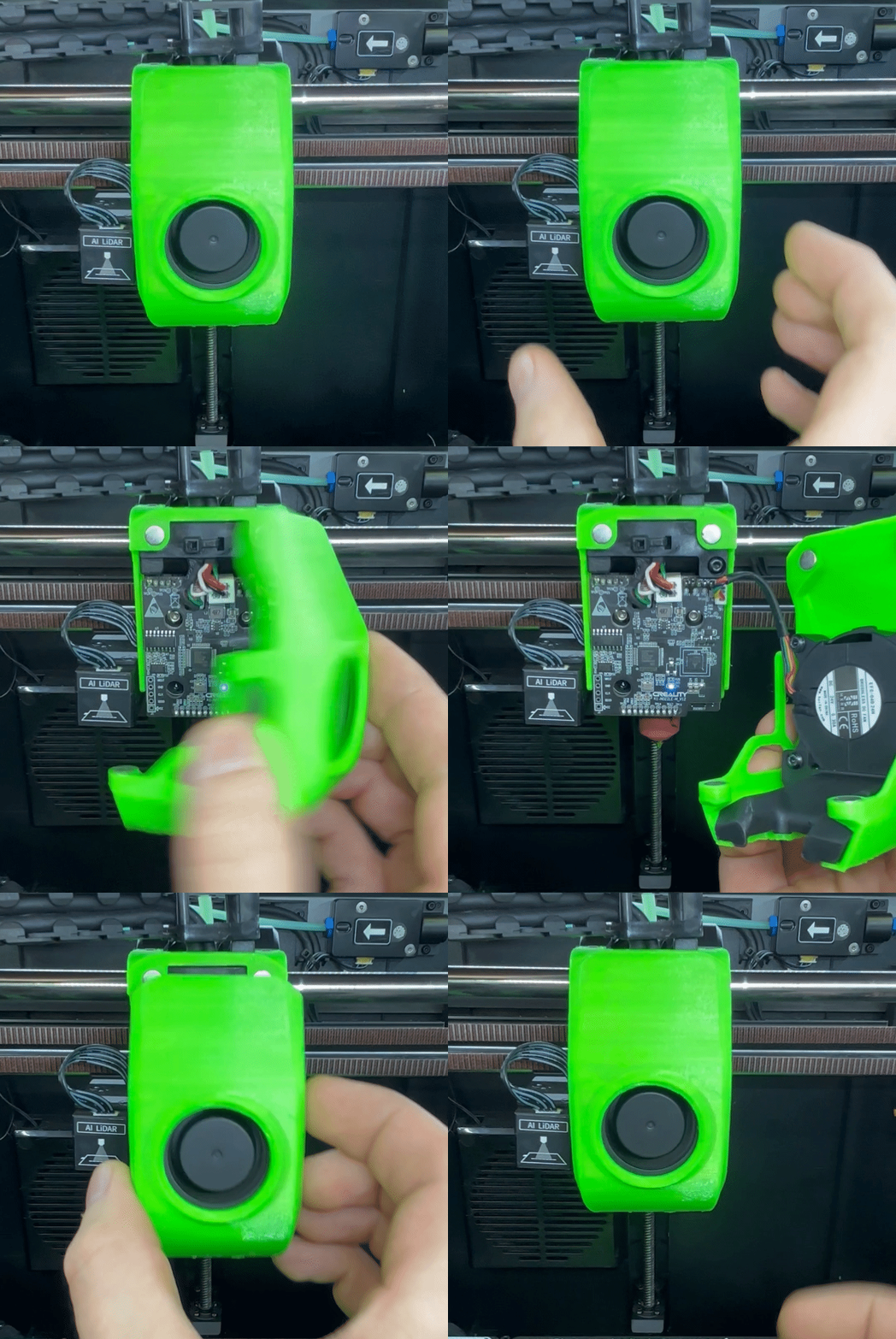
3.3 You can now reassemble the extruder, mount it onto the carriage and connect the sensor and the stepper motor to the the toolhead pcb.
4. Klipper Config
Inside printer.cfg file, find the [filament_switch_sensor filament_sensor_2] settings and replace them with the following code :
[filament_switch_sensor filament_sensor_2] pause_on_runout: true switch_pin: !nozzle_mcu:PA10 event_delay: 1.5 pause_delay: 0.25 insert_gcode: M118 filament inserted LOAD_MATERIAL runout_gcode: M118 filament runout {% if printer.extruder.can_extrude|lower == 'true' %} G91 G1 E-30 F180 G1 E-50 F2000 G90 {% endif %} If you have an older version of the firmware where only [filament_switch_sensor filament_sensor] is defined, you can replace it with the following code :
[filament_switch_sensor filament_sensor] pause_on_runout: true switch_pin: !nozzle_mcu:PA10 event_delay: 1.5 pause_delay: 0.25 insert_gcode: M118 filament inserted LOAD_MATERIAL runout_gcode: M118 filament runout {% if printer.extruder.can_extrude|lower == 'true' %} G91 G1 E-30 F180 G1 E-50 F2000 G90 {% endif %}
M118 :
If you get an error M118 unknown command you need to add [respond] on a new line in your printer.cfg . More info about respond command here .
insert_gcode :
M118 filament inserted will display the message “filament inserted” inside the console. This is useful for testing that the sensor is working correctly.
LOAD_MATERIAL allows to load automatically the filament once it's detected by the sensor. The only downside is that the default temps is 240°C which is a bit high for PLA.
5. Slicer settings recommendations
I recommend you to disable arc fitting.
This settings allows arc gcode commands (G2 & G3) to be generated in addition of the linear movement commands (G0 & G1). This feature is nice for reducing the weight of the gcode files.
But when the runout sensor is so close to the driving gears, there is not much filament left between the sensor and those gears when the runout is detected. And the print can only be paused between two gcode commands.
In the worst case, if the runout is detected when you are printing a perfect circle, its diameter can be printed with only one arc command. This command will more likely require more than the remaining filament. The filament will pass the gears before the print is paused. Therefore it will be impossible to retract it afterwards. And bigger is the circle, bigger are the chance for this to happen.







Names are used only to indicate the source of a result. Polyzon is not affiliated with the listed sites.