
Free 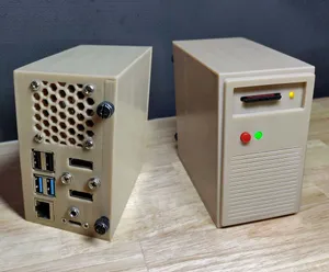
Raspberry Pi 4 case - Retro tower desktop
Printables


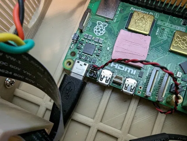


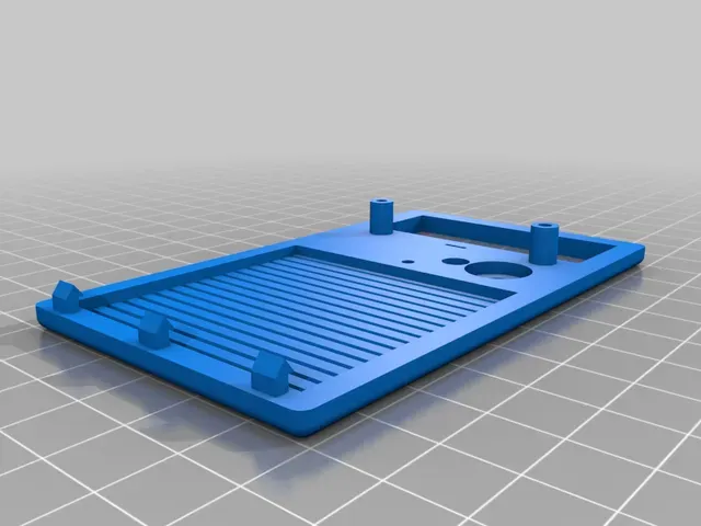


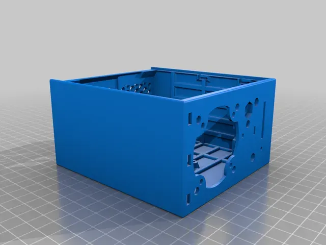

A retro style beige Raspberry Pi 5 tower case. It has a working power button, LED, and IO activity LED. The SD/microSD card can be inserted like a floppy disk to swap between different operating systems. It also has 2 HDMI ports, audio jack, and USB-C power on the rear of the case.
There is space for a 40mm exhaust fan and a 40mm or 50mm front intake fan. There is also enough space for a large cooler like the ICE tower.
Parts needed (links at the end):
Micro SD to SD Card extender: 1
Micro HDMI to HDMI Adapter Cable: 2
Panel-Mount USB-C Extention Cable: 1
40mm 5V fan (for exhaust): 1
Low-Profile CPU Cooler or ICE Tower Cooler: 1
SPST Momentary Mini Push Button: 1
5mm LED with resistor: 1
3mm LED with resistor: 1
#6-32 UNC thumbscrew (standard PC case screw): 2
#6-32 UNC screw or M3 screw (standard PC case screw): 6
various wire/header connectors (for connecting fans/LEDs/power button)
Optional:
Front 5V 40mm/50mm fan: 1 (note: I've not needed this even when overclocking the Raspberry Pi)
Noctua NF-A4x10 to replace CPU Cooler fan: 1
Assembly instructions
Prepare all parts
note: any places that require screwing plastic parts together can be replaced with glue if you are way too confident/lazy.
- Print out all parts with whatever material/color you would like.
- (optional but helpful) Use a thread tap on all screw holes
Start Assembly
- Add header pins to jumper J2 (right between USB-C connector and HDMI-0). These are for the power button.
- Tap threads for all screws. You may be able to tap threads by forcing the screws into the holes.
- Tap threads for push button. If you don't have a tap, you can use the push button to create the threads. You may need to use a file to help make sure the push button fits if you don't have a tap.
- Press fit 3mm LED into the main case. Glue can be added, but the press fit should hold it fine.
- Press fit 5mm LED into the main case. Glue can be added, but shouldn't be needed.
- Put SD card extender in the SD card tray and attach to the case with screws or glue. This may require a long screw driver that can reach through the fan grill or a very short one that will fit in the case. This is easer to do before anything else is in the way.
- (Optional) Attach front fan with screws
- Screw/Glue in front panel. Make sure LEDs are visible and the push button does not get stuck.
- Put HDMI adaptors in the HDMI holder, but don't mount it in the case.
Connect wires to the GPIO Header
- (Optional) Make a simple splitter for the CPU/Case fan(s).
- The push button goes across pin5/pin6 (polarity doesn't matter).
- The power LED goes to pin8(+) and pin14(-).
- The GPIO LED goes to pin37(+) and pin39(-).
- Connect all wires, connectors, and micro SD card extender to the raspberry pi before carefully placing it in the case. At this point all cables/extenders should be connected to the Raspberry pi, but not the case. (note: if using the ICE or low profile heatsinks, they should not be attached at this point)
Finish Assembly
- Use the brass spacers/mounts/standoffs from the cooler to screw the Raspberry PI to the case. These 4 brass pieces should now be going through the Raspberry Pi's mount points into the case.




Names are used only to indicate the source of a result. Polyzon is not affiliated with the listed sites.