
Free 
Creality K1, K1c, K1 Max & K2 SE Door Hinges Geared Print in Place
Printables








I CANNOT SAY THIS ANY SIMPLER. I'M WRITING THIS IN UPPER CASE SO THAT WHEN SOMEBODY SAYS ‘I DON’T UNDERSTAND WHAT I NEED TO PRINT' I CAN SAY IT'S ALL IN THE INFORMATION PAGE. AT A BARE MIMIMUM, EVEN IF YOU DON'T READ ANY OF THE MAIN TEXT, PLEASE READ THE 4 BULLET POINTS HERE. K1 and K1C owners, pay particular attention to bullet points 2 and 3.
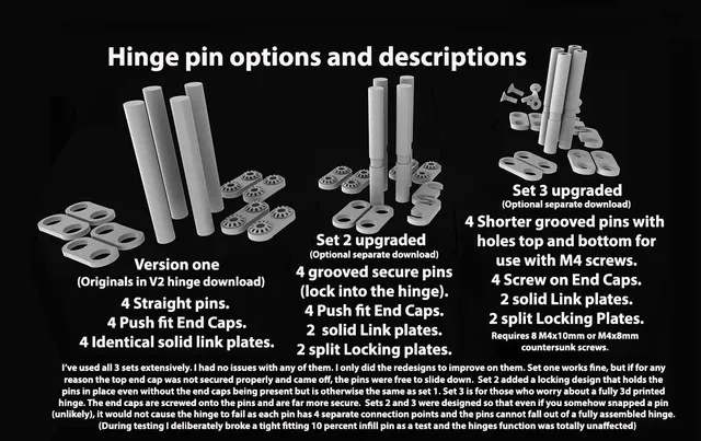
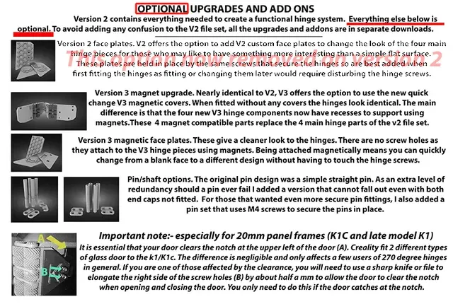
- For older K1 and all K1 Max printers, All the files in this file set when printed will produce every print part needed for assembling a complete pair of hinges. - For more recent K1 printers and ALL K1C printers , you will NEED 2 different side panel hinge pieces (available in a separate file set elsewhere in my downloads and linked below in the main text) these replace the 2 side panel pieces of this file set. All the other parts of the hinge assembly remain the same. - K1 owners please note:- Creality starting using K1C frames on the K1 shortly after the K1C was released. Check which case your printer uses before you print the parts. These 2 hinges affix to the left side of the printer using the two corner screws that hold the side panel in place. On older K1 models, the spacing between those holes in the corners is around 6cm (around 2 and a half inches), these older cased printers need nothing extra and can happily use all the files already here to print their hinges. The K1C and subsequent releases of the K1 use a 2cm spacing for those screws (around 3 quarters of an inch). Those with the K1C case type 2cm hole spacing WILL NEED the 2 replacement parts from the K1C adapters download to assemble the hinges for use on their printers. From info given by users out there, there are 2 versions of the k1c case. one has the door glass holes offset to one side by around half a millimeter. This means that although most k1c case owners can fit the hinges without any issue, a small proportion may find that their glass holes are .5mm offset to the side. If this affects you, just file the hole/slot of the printed part that connects to the glass to widen the slot by half a millimeter. NOTE:- if that gap is any larger than .5mm then the hinge is assembled incorrectly! Even one tooth out in the gear mesh will affect the offset by around 1 - 1.5mm and can drastically affect clearances while also incurring door misalignment where it closes against the printer frame. Regardless of which printer you use (K1/K1C/K1 Max) …..I t is essential that the hinge be assembled correctly!…. Check the pictures provided with this download for better detail on correct assembly of the hinge halves. - During later revisions of the hinge design that were initially for my own use and required longer term testing before release, I created a number of files that could also be used as updates and upgrades to this version of the 270 degree hinges (V2 worked perfectly and I didn't want to change anything in the main file set of the V2 hinges). As a result there are now 2 different ‘optional sets’ of hinge pins for those who may prefer the pin improvements over the more simple straight pins of the V2 hinges originals. YOU DO NOT NEED THEM! If for any reason you see those upgrades and feel they add some kind of confusion, then you can happily ignore their existence and stay with the pins supplied in this V2 file set. I HAVE ADDED SOME MORE SIMPLIFIED INSTRUCTIONAL IMAGES TO THE MAIN PICTURES. THEY ARE THERE SOLELY TO KEEP THINGS AS SIMPLE AS POSSIBLE FOR THOSE WHO DON'T WANT TO READ ALL THE DETAILED STUFF.
-----------------------------------------------------------------------------------------------------------------
If You find this design useful, Please consider leaving a like, sharing a make, or leaving a comment (enough likes earns me a discount on a roll of filament, and in designs like this I go through a lot of it).
-----------------------------------------------------------------------------------------------------------------
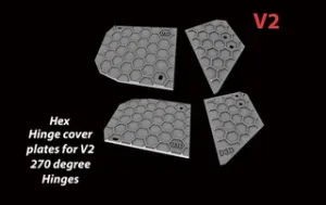
This is version 2 of the 270 degree hinges (V1 is now deleted). Version 2 has been downloaded around 2000 times now and is a tried and trusted design. As such I no longer touch this file set as I do not want to risk changing anything that may potentially introduce problems. Until recently there was an option on the V2 hinges to use additional face plates to change the look of the hinges. Unfortunately a very small number of people complained that they were confused by the additions and options over and above the stock requirements needed to complete a set of hinges and as a result I have removed the majority of extras that were once available on V2. Hopefully this will solve the confusion issues once and for all.
The 2 later pin design options I created after V2 went live are still available for download and use in my other downloads, but I stress again, they are NOT needed and remain solely for those who may prefer their design to the more simple straight pins of the V2 file set.
PLA PETG ASA .4 nozzle .2 layer
IMPORTANT NOTES :-
It is worth noting here that some sellers of Acrylic replacement K1/K1C doors make a point that the K1 and K1C actually use slightly different doors to each other. The difference is minimal but enough to bring the door notch into play as a potential issue, along with the screw holes between K1 and K1c also being around half a millimetre different laterally. I adjusted the fitting holes to find the middle ground so no adjustment beyond that already built in to the hinges should be needed. I can only see one potential issue and that is if Creality fit a K1 door to a K1C or vice versa. The potential for a clearance issue arises if they do that so in a worst case scenario you may have to file the screw slots of the door hinge piece to account for that half millimetre.
----------------------------------------------------------------------------------------------------------------
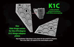
K1C owners (and newer K1 printers using the 20mm spacing on the printer side panels) WILL NEED the K1C adapters in order to be able to use these hinges. They are available here:- K1C adapters for use with geared 270 degree door hinges The two parts from there replace the two side hinge parts of this file set (The half of the hinges that attaches to the side of the printer).
----------------------------------------------------------------------------------------------------------------
MAIN DESCRIPTION
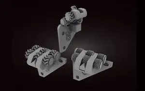
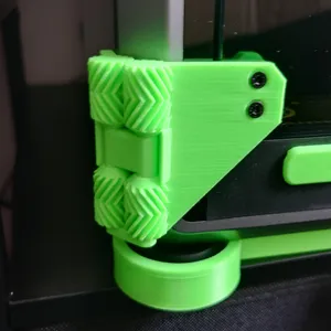
A 270 degree geared door hinge design for allowing K1 and K1 Max owners to open the glass door and swing it fully open through 270 degrees and allow it to rest against the side panel instead of being at risk from damage at the the normally stock 90 degree maximum. The gif used in the photos to demonstrate the hinge range is the later version 3, but it is functionally identical to version 2 in door operation. Version 3 just has additional ‘beauty’ plates.
Being component form and not 'Print in Place' makes it is an easier print and more importantly allows for more exotic filaments than PLA to be used if desired. Print in Place hinges often fuse together with even fairly simple filaments like PETG. Printing the hinge in individual parts removes the problems of that potential issue.
The files in this specific set are for the Early models of the K1 and ALL versions of thee K1 Max! The 2 different parts needed to adapt this hinge set work with the K1C and later releases of K1 printers (that Creality switched to the K1C frame) are in the link above the ‘Main Description’ title further up this page.
Until recently I was using mordeivs ‘print in place’ 270 degree hinges and I'd liked the function of those so much at the time of printing that I created two geared latches to follow the overall design but with my own twist. Both catches work with these new hinges and are on my profile models. The first design was the 'Penwald' Door catch followed by the more over engineered 'Vorlon' Door catch. For those wanting to securely hold the door in place at the side of the printer after fitting 270 degree hinges? they are both worth a look. The catches have universal mounting plates to allow for use on all 3 current K series printers (K1.K1C/K1 max). Creating those catches made me realise I could make my own version of the hinges and set me off on a nightmare journey that only ended as I uploaded the last revision (V3).
Both hinges comprise of :- Two Main hinge parts, 2 hinge pins, 2 central link plates and 2 end locks. There is also an optional puck cover that can be used with the puck to hold the nuts in place so they cannot fall out during assembly. It is not necessary, but when I was doing multiple test prints and had the door on and off a lot, it saved me a lot of time looking for the nuts when they fell out.
Parts are (hopefully) in the orientation that they should be printed. The hinges should be printed stood on their edge with the gears obviously pointing upwards. Because of the two gaps in the gears you will need supports there. After numerous updates it is possible I may have at least one upside down. Use common sense and rotate it if that has happened and I've missed it.
The only other parts needing support are the End locks (the parts that fit to the hinge pins top and bottom). They should be printed flat but this means the two holes underneath in each will need support adding. These end parts were designed to fit the pins tightly making glue an option rather than a requirement. For the belt and braces brigade, you can obviously use glue to permanently attach them.
Note: Since creating this version I have created 2 sets of modified hinge pins in a separate file set for those wanting them. The difference being that the new pins feature a clip that holds the pin in situ even without the end locks in place. They are an OPTIONAL upgrade but may be worth considering, especially for those who don't want to use glue but may also have concerns about the potential for the end caps coming loose (which they shouldn't as they are tight AF even without glue).
Additional recommended parts :-
- 4 x M3 10mm for the sides. - 4 x M3 16mm (or 18mm) screws for the glass door (k1/K1C owners, make sure that the screws you use for attaching the door to the hinge do NOT touch the printer belts when the door is closed. If in doubt, trim the upper door screws to sit flush with the door puck. This potential clearance issue does NOT affect K1 Max printers. - 4 x M3 nuts are also needed for the puck behind the glass door for the hinge screws to attach to. I know this is probably obvious but it needs saying anyway. The tempered glass door is very easy to break. Handle it carefully.
Print information :-
Print both Hinges (Each hinge is in 2 parts, one for the side panel and the other for the door). Print them upright with the flattest portion closest to the bed for the best adhesion and less support material needed. These parts are not interchangeable between top and bottom hinges so don't mix them up. Print at a minimum 40 percent infill and with 3 walls.
4 Hinge pins, 2 per hinge and all are identical. Again at a minimum 40 percent infill. Print upright. For reference, I have never had any issues of failure in the PLA hinge pins provided that they move freely in the hinge on assembly. Any tightness will add torsional stresses that could sheer the pin. If you cannot easily rotate the pin in situ by hand, then get the sandpaper out and get it to turn freely. I recently changed the PLA pins out for a set of ASA prints as I was using up the remains of an ASA roll. The PLA pins I removed showed no sign of wear despite many months of use.
4 Centre plates , 2 per hinge. All identical). Print flat.
4 Locking plates/End Caps ( 2 per hinge. All identical) 40 percent infill. Print flat with the holes facing the bed (and use supports for those holes).
2 Pucks for the other side of the glass to hold the nuts the hinge screws to. ( 1 puck per hinge. both identical). minimum 30 percent infill, Any layer height.
2 ‘'OPTIONAL’ nut trap covers that prevent the nuts falling out of the pucks during fitting to the door. You are theoretically only fitting the hinges once so the nut traps are likely overkill and a bit of tape would hold the nuts in place just as well. Use them, or Don't. Totally up to you.
Post processing if required:-
Remove any and all support material. I initially ran a screwdriver through the hinge gears in case of any rogue support material (Creality Print auto support adds some hard to remove support in there that needed removal). Test fit the pins through the hinge gears and centre plates.
I designed this so that if for any reason your tolerances are wonky and the pin is too tight? the nuclear option allows for using an 8mm HSS drill bit to chase the gear holes through. I only had to do this on one particular piece of my many test prints. I ran the bit through by hand, gripping the drill bit in a pair of vice grips and slowly sending it through. The blockage on that one part being some reluctant support material inside the single middle gear (the hardest to get to).
It is essential that the pins move freely in the hinge portions. You don't want the pins too tight as the pins will be held solidly in place by the top and bottom end caps, the hinge portions are designed to rotate around the pins. If the pins are too tight in the hinge pieces, the hinge will try to rotate around the affected pin/s in the end caps. Given how tight the end caps were designed to hold the pins (to avoid needing glue) you potentially run the risk of sheering a tight fitting pin if it is binding on the hinge. I found on a number of test prints that were tighter than I would like, that working the hinge back and forth a few times while assembled and off the printer was enough to get them moving freely.
Assembling the hinges:-
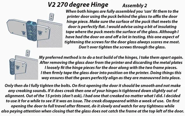
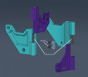
I have added a picture based assembly sheet to the main images of the download for those who may prefer it in image form.
Take one half of a hinge, one hinge pin and two centre plates (the parts like a bike chain link). Thread the pin through the gears capturing the centre plates with the pin as you do so.
Take the other half of the hinge and align it as straight as possible (with the gears meshed). It may not be 100 percent perfect alignment but near straight as dammit is close enough. Check the pictures to see what I mean there regarding the alignment if you need a visual aid, I added a photo showing the correct alignment and also showed how it could be done wrong, wrong alignment will at a minimum, stop the door fitting correctly.
Slide the second pin in place through the gears and centre plates. The plates will then lightly hold the 2 halves in place as long as you don't let the pins slip back out at this point.




Names are used only to indicate the source of a result. Polyzon is not affiliated with the listed sites.