
$ 8.00 
zBrace for Creality Ender V3 SE/KE
Printables
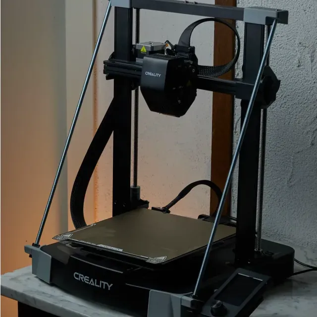
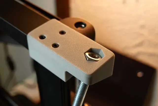
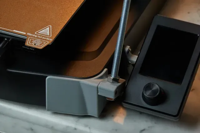
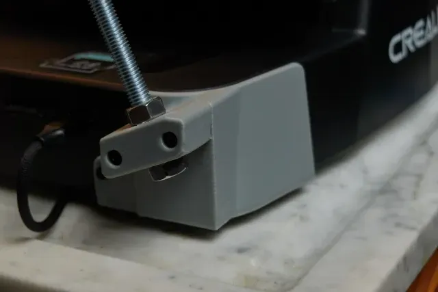
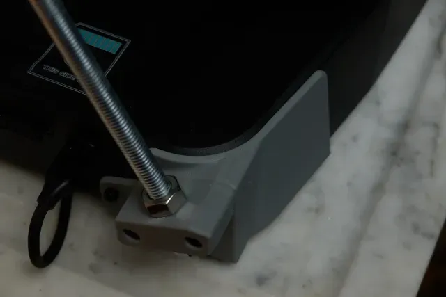
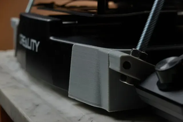
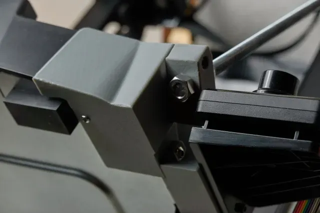
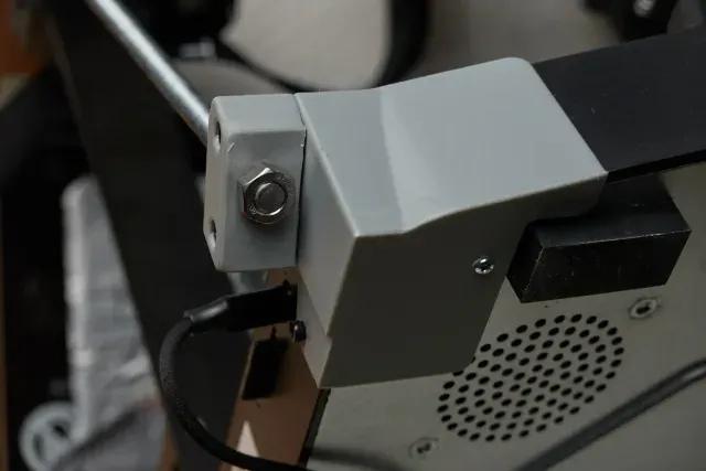
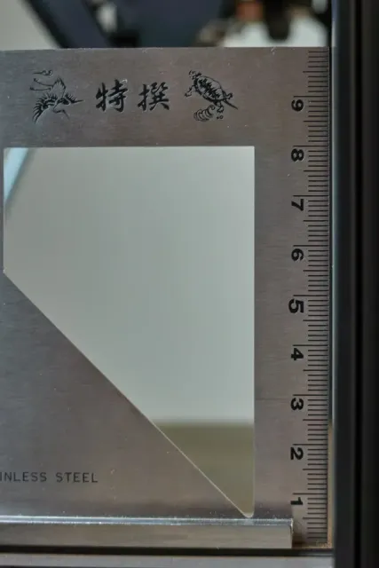
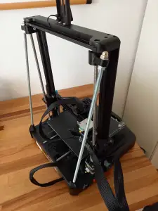
My Ender V3 SE’s gantry was completely out of whack. maybe 92° leaning to the back. So I looked for solutions. I did not find one I liked. It took me about a week to design and test this.
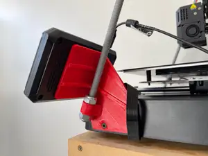
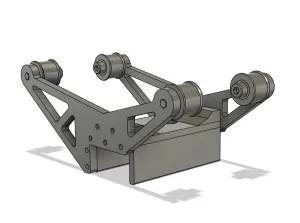
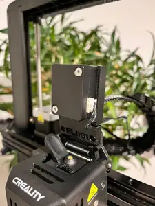
The braces fit precisely to the Ender’s plastic parts (top gantry brace and base). By having a tight fit, there is no wiggle whatsoever. It took me quite a while to model the exact form of the Ender V3 SE base.
Adjusting the Gantry in either direction is super easy by just adjusting the bottom 2 M8 nuts.
I chose to attach the rods to the front of the base, because of the better angle (23.5°).
Main features
Only one hole has to be drilled, since the bottom braces use the holes on the bottom and the existing holes for the screen attachment.
The top nuts are fixed. Adjustments are made with the lower 2 nuts.
No supports needed for printing.
Total of 118g of Filament needed and about 5h of printing
Hardware needed
- 1m M8 thr e aded rod (yes, it is designed for exactly 50cm rods)
- 4x M3X5X5mm Heat-Set inserts
- 4x M3 10mm
- 4x M3 20mm
- 8x M8 nuts
- 1x M3 nut
- M3 drill bit and drill
Printing
I provide a .3mf file. I used modifiers to enfore critical parts.
Use 0.2mm layer height. I printed it using a 0.6mm nozzle. 0.4 works fine too.
I used PLA+ and it’s sturdy enough.
Assembly
Here’s two animations on how to assemble it.
Top and bottom left braces.
The bottom left brace is the one that you need to drill a hole into the base for.
I chose to use an M3 10mm screw and nut to fasten the left bottom brace from the side. Add a washer if you like. The base’s wall is just 3mm thick.
You just remove the screws from the bottom metal plate of the base and slide it back a bit.
(ATTENTION: disconnect power before.)
It may be neccessary to remove the bottom rubber feet and move them a bit. Mine were not located symmetrically.
Note: I used the the screws that were in the bottom metal plate. It works fine. You can however replace them with slightly longer ones if you’re worried.
The right braces attach the same way, except the bottom brace just uses the 3x M4 screws from the screen assembly. You can stick a allen key through the M3 holes the screen attaches to. Attach the screen assembly with M3 10mm screws. Don’t overtighten, or you’ll wear out the threads you cut into it.
Adjusting the Gantry
If the gantry is leaning towards the front, you use the bottom UPPER M8 and turn it clockwise towards the bottom brace (seen from above) to push the rod upwards. If the gantry leans towards the back, you turn the LOWER M8 screw clockwise (seen from below) to pull the rod down.
When you’re satisfied with the 90° angle, fasten both nuts. Done.
In addition to having a perpendicular gantry you’ll also have less vibration in it.
Let me know how you like it.
If you have questions, ask away. I am here to help.


Названия используются только для указания источника результата. Polyzon не аффилирован с перечисленными площадками.