
Бесплатно 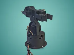
BRACHIUM - 5 DOF Robotarm
MakerWorld
%2Fhttps%3A%2F%2Ffbi.cults3d.com%2Fuploaders%2F52110506%2Fillustration-file%2F0787d7d6-267d-45e9-bad8-f2af80d2dc5a%2F00_PK1597_01_hero.jpg&w=640)
%2Fhttps%3A%2F%2Ffbi.cults3d.com%2Fuploaders%2F52110506%2Fillustration-file%2F18deb9f5-dd57-4157-b145-f45876097830%2F01_PK1597_02_pick_and_place_gripper.jpg&w=640)
%2Fhttps%3A%2F%2Ffbi.cults3d.com%2Fuploaders%2F52110506%2Fillustration-file%2F004ed510-e18e-4ad2-8576-8e77ba316a13%2F02_PK1597_03_full_reach_side.jpg&w=640)
%2Fhttps%3A%2F%2Ffbi.cults3d.com%2Fuploaders%2F52110506%2Fillustration-file%2F770aebb9-20bc-4059-980e-2db1226e4db5%2F03_PK1597_04_back_cable_channels_spring.jpg&w=640)
%2Fhttps%3A%2F%2Ffbi.cults3d.com%2Fuploaders%2F52110506%2Fillustration-file%2F3fc91d47-a6e6-42e7-ba1d-17c60b7b4964%2F04_PK1597_05_electronics_base.jpg&w=640)
%2Fhttps%3A%2F%2Ffbi.cults3d.com%2Fuploaders%2F52110506%2Fillustration-file%2Fec4169e9-95d0-4e8b-88ee-2dff5288e460%2F05_PK1597_06_exploded.jpg&w=640)
%2Fhttps%3A%2F%2Ffbi.cults3d.com%2Fuploaders%2F52110506%2Fillustration-file%2F041b7895-1141-425f-852d-59eb60b0c8c7%2F06_PK1597_07_print_layout.jpg&w=640)
%2Fhttps%3A%2F%2Ffbi.cults3d.com%2Fuploaders%2F52110506%2Fillustration-file%2F06ede307-e2d3-48ce-9158-2111c4ab44f8%2F07_PK1597_08_section_turret_forearm.jpg&w=640)
%2Fhttps%3A%2F%2Ffbi.cults3d.com%2Fuploaders%2F52110506%2Fillustration-file%2F5a3befb5-fecd-450f-9389-cb05cb933993%2F08_PK1597_09_colour_variant.jpg&w=640)
%2Fhttps%3A%2F%2Ffbi.cults3d.com%2Fuploaders%2F52110506%2Fillustration-file%2F2c0730ce-98f7-40f1-baf8-43b179128a61%2F09_PK1597_spec_card.jpg&w=640)
A complete 6-axis desktop robot arm that you print yourself and build with standard hobby servos: 3 x MG996R for the base, shoulder and elbow, and 3 x SG90 or MG90S for the wrist and the gripper. The base turns on a real 6806 thin-section bearing plus six 608 rollers, the shoulder and elbow run on 608 bearings, the gripper is a true parallel rack-and-pinion gripper, and the base is an electronics box for a PCA9685 servo board and an Arduino Nano or ESP32. Reach is about 300 mm to the centre of the gripper fingers. Every part prints without supports.
**How it works** - Base yaw (J1): the MG996R sits in the base and its horn is screwed to a printed hub that runs in a 6806 bearing (30 x 42 x 7 mm). The turret also rolls on six 608 bearings on M8 axles, so the tipping load goes into the base and not into the servo - Shoulder (J2) and elbow (J3): MG996R servos. One side of each joint is the servo with a standard 25T aluminium disc horn (24 mm, 4 x M3 on an 18 mm circle) screwed into a centring recess, so no printed splines. The other side runs on a 608 bearing and an M8 bolt - Wrist pitch (J4) and wrist roll (J5): SG90 or MG90S servos with the double-arm horn from the servo bag, screwed into a shaped recess - Gripper (J6): an SG90 turns a printed m1 20-tooth pinion between two racks, so both jaws move in and out together and stay parallel. The jaws open from 0 to 40 mm and slide on tongue-and-groove rails - Optional counter-balance: a 0.8 x 8 x 30 mm extension spring between a lever on the shoulder bolt and a post on the turret. It takes about 3 kg.cm off the shoulder when the arm is straight out - The arm links are U-channels open at the back. The servo leads run inside them under snap-on clips, drop through a hole in the turret and an arc slot in the base deck, and go to the boards in the base
**Range of motion (checked in CAD)** - Base yaw -90 to +90 deg, shoulder -87 to +90 deg, elbow -51 to +128 deg, wrist pitch -55 to +90 deg, wrist roll -90 to +90 deg, gripper 0 to 40 mm
**What is in the kit (17 printed parts)** - Base housing (dark grey) with mounts for the yaw servo, a PCA9685 board and a 50 x 70 mm perfboard for the Nano or ESP32, a DC jack hole, a rocker switch cut-out, a USB slot, vents, 4 desk-screw holes and recesses for rubber feet - Base deck (dark grey) with the 6806 seat, six 608 roller brackets, the cable arc slot and an engraved yaw scale. Bearing retainer and yaw hub (orange) - Turret, upper arm and forearm (white). Shoulder lever, elbow spacer and wrist bracket (orange) - Gripper body and rail (dark grey), pinion (orange), left and right jaws (white) - Cable clip (print as many as you need) and a tolerance test coupon
**Hardware you need (not included)** - Servos: 3 x MG996R, 3 x SG90 or MG90S (MG90S recommended for the wrist pitch), 3 x 25T aluminium disc horn for MG996R (24 mm, M3 holes on an 18 mm circle) - Bearings: 1 x 6806-2RS (30 x 42 x 7 mm), 8 x 608ZZ (6 rollers, shoulder, elbow) - M8: 8 x M8 x 30 bolt, 6 x M8 nylock nut, 2 x M8 nut - M3: 12 x M3 x 6 (horn screws), 12 x M3 x 12 (MG996R mounting), 3 x M3 x 12 (turret to hub), 3 x M3 x 8 (bearing retainer), 4 x M3 x 10 (deck), 2 x M3 x 12 (gripper rail), 1 x M3 x 12 (wrist pivot), 2 x M3 x 16 (spring pins, optional) - SG90 screws from the servo bags (2 mounting screws and 2 small horn screws per servo) - Optional: 1 x extension spring 0.8 mm wire, 8 mm OD, 30 mm long (from a common spring assortment) - Electronics: PCA9685 16-channel servo board (4 x M2.5 x 6), Arduino Nano or ESP32 DevKit on a 50 x 70 mm perfboard (4 x M2 x 6), 5.5 x 2.1 mm panel DC jack (8 mm hole), KCD1 rocker switch (19 x 13 mm), 5 V or 6 V 5 A power adapter, 1000 uF capacitor for the PCA9685, 3 x 30 cm servo extension leads for the wrist and gripper - 4 x M4 or #8 wood screws to fix the base to a desk (recommended), or 4 rubber feet 10 mm - Firmware is not included. Any PCA9685 servo sketch works, for example with the Adafruit PWM Servo Driver library
**Checked in CAD** - Every joint was moved through its full range in 37 steps, and the arm was also checked in 43 mixed poses. Every printed part, servo, horn, bearing, bolt and screw was tested against every other one: apart from the rollers on their track and the bearing rings, no part touches another (0 mm3 overlap). The smallest running clearance is 0.3 mm - Rack and pinion: contact ratio 1.77, 0.25 mm backlash, no overlap over the whole stroke. The rack tongues slide in their grooves with 0.25 mm per side - Cable paths over every joint stay clear of the parts. The leads need about 20 to 50 mm of slack at each joint (the base needs the most) - Holding torque with the arm straight out (worst case): shoulder 4.9 kg.cm without the spring and 1.7 kg.cm with it, elbow 1.6 kg.cm, wrist 0.3 kg.cm. MG996R stall torque is 9.4 kg.cm at 4.8 V and 11 kg.cm at 6 V - Payload: about 120 g at full reach with the spring, keeping every servo at or below half of its 6 V stall torque (about 20 g without the spring). Closer in, it can lift more. This is a learning and demo arm, not an industrial one - The base does not tip over with 150 g at full reach in any direction, but we still recommend screwing it to the desk
**Printing** - No supports. 14 parts print as they come. The cable clip and the two jaws are small: use a 5 mm brim - Slice-checked in PrusaSlicer: PETG, 0.2 mm layers, 3 walls, 15 percent infill, about 580 g and about 50 hours for all parts. The biggest part (the base housing) is 176 x 176 x 58 mm and fits a 180 mm bed - The 3MF has three colours: white, dark grey and orange - Fits: 0.1 mm per side for the bearing seats, 0.3 mm for the horn recesses and servo windows, 0.25 mm per side for the rack rails - Print the tolerance coupon first (about 15 minutes). Check that the 6806 and 608 bearings press in, that the aluminium horn drops into its 24.6 mm ring, that the SG90 horn fits its outline, and that an M8 and M3 bolt fit their holes
**Assembly** 1. Press the 6806 into the deck and screw the retainer on. Push the hub in from below 2. Mount the yaw servo in the base, fit its horn, set the deck on and screw the horn to the hub from inside the hub. Screw the deck down 3. Fit the six 608 rollers on M8 bolts. Put the turret on and screw it to the hub 4. Mount the shoulder servo, fit the 608 in the right cheek, screw the upper arm to the horn and fit the M8 bolt with the lever 5. Do the same at the elbow with the forearm, its servo, the 608 and the spacer 6. Fit the wrist pitch servo, the bracket, the roll servo and the gripper 7. Build the gripper: servo, pinion on its horn, jaws in the rails, rail screwed on 8. Run the leads in the channels, snap the clips on, wire the PCA9685 and the Nano or ESP32, add the spring if you want it
Note: original design built from scratch in Blender; designed and slice-checked in PrusaSlicer, mechanism checked for collisions in CAD; this exact version has not been test-printed yet.


%2Fhttps%3A%2F%2Ffbi.cults3d.com%2Fuploaders%2F52110506%2Fillustration-file%2F0df84f51-8fc6-47f9-9f61-12ec68adc0e7%2F00_PK1924_01_hero.jpg&w=300)
%2Fhttps%3A%2F%2Ffbi.cults3d.com%2Fuploaders%2F36481470%2Fillustration-file%2F73784ced-be81-4aea-8181-00df02b690fe%2F6229-hero.jpg&w=300)


Названия используются только для указания источника результата. Polyzon не аффилирован с перечисленными площадками.
Комментарии 0
Загружаем комментарии…