
Бесплатно 
Smart Self-Watering Planter | Modular No-Pump Design
Thingiverse
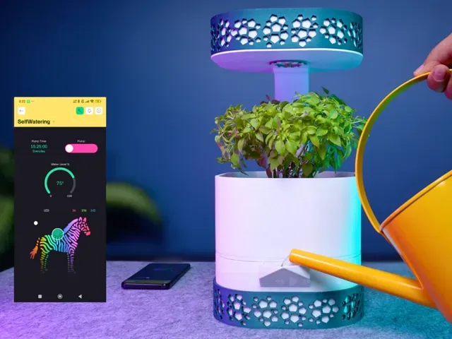
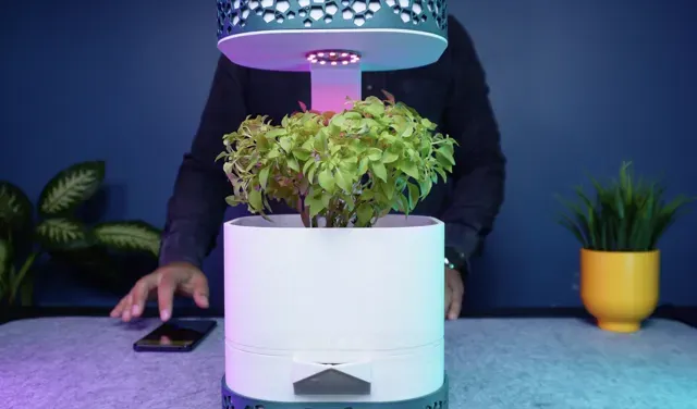
A simple idea and a 3D printer… The result?
Hey friends, I love my plant but sometimes I forget to water it. As a maker, I thought, I really need to find a solution for this.
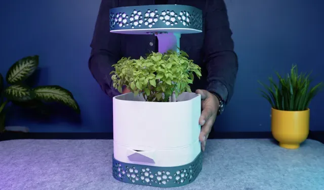
So I decided to design a self-watering smart planter. At the bottom there is a water tank, above that a soil container, and on top an electronics enclosure. All of them are connected with a vertical support piece that also hides cables and hoses.
My biggest helper in this process was the Bambu Lab A1 Combo…
The prints came out strong and reliable. Still, to make sure the water tank is fully sealed, I applied a thin layer of epoxy resin inside it. The tank needs to dry for twenty four hours, so while it cures, let’s continue with the assembly.
First I attach the soil container to the vertical support using M three screws and nuts. This makes the structure solid and stable. Then I carefully move the plant into its new container, add some extra soil to support the roots, and the planting is complete.
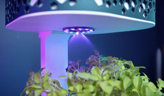
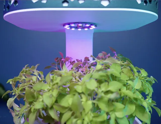
Before adding the electronics, I install the RGB ring LED. After that, the electronics enclosure is fixed to the vertical support with M three screws. With the main parts together, I add a decorative frame around the electronics enclosure. Its mosaic like pattern makes the whole build cleaner and more stylish.
Next comes the spray nozzle. It has two modes, a tight pressurized jet for direct watering or a softer spray that creates a gentle rainfall effect over the whole plant. This way watering is both effective and elegant.
Adjustable 2-4 Bar Low Pressure Spray Nozzle:
- Nozzle 1 - https://share.temu.com/mQbTOvtQnRC - Nozzle 2 - https://amzn.to/4mXgzKj - Nozzle 3 (It was used in the project, but it can also be found in a local shop) - https://sismist.com.tr/dusuk_basinc_spreyleme_nozulu_pirinc_ayarli_2-4bar_civi_baglanti Finally I mount the water pump inside the electronics enclosure and secure it with screws. I measure and cut the hose for the nozzle, tighten it with a cable tie so it stays in place, and guide the inlet hose through the channel in the vertical support down into the water tank. Now the water system is fully connected.
DP-2FM 15V Water Pump (or similar 12V and approximately 3 bar pressure power is ideal)
The DP-2FM 15V DC Water Pump is a water pump that can be used for water transfer in various electronic projects. It has a DC 15V operating voltage. It features a flow sensor (but we are not using a flow sensor in the project)
Technical Specifications:
- Model: DP-2FM Series: 03 - Flow Rate: 430-530 cc/min - Max. Pressure: 3 bar - Current: <300 mA - Noise: 55 dB - Voltage: 12V DC Dimensions:
- Motor Diameter: 27mm - Motor Length: 60mm - Water Inlet Diameter: 4.9mm - Outlet Diameter: 6.4mm Water Pump (or similar):
- Water Pump Model 1 - https://amzn.to/4oe9Blf - Water Pump Model 2 - https://amzn.to/3WvWUXc - Water Pump Model 3 (It was used in the project, but it can also be found in a local shop) - https://www.motorobit.com/dp-2fm-15v-water-pump-with-flow-sensor Now it is time to make this project smart. On the breadboard I am using a Wemos D1 Mini Wi Fi board, together with a voltage regulator and a MOSFET to drive the pump. For water level detection I added a simple analog sensor, extended with jumper wires.
Circuit Assembly
Follow these steps carefully to assemble your Automatic Plant Watering System. Double-check component orientation (especially diodes, electrolytic capacitors, and the MOSFET).
Power Supply Section:
- Input Connector (U3): Connect your 12V DC adapter (positive to pin 1, negative to pin 2). - Decoupling Capacitor (C4): Place a 470µF electrolytic capacitor directly across the 12V input for stability (observe polarity: + to +12V, – to GND). Voltage Regulation for Wemos + NeoPixel:
- Regulator (U4 - L7805): Pin 1 = 12V input
Pin 2 = GND
Pin 3 = +5V output
- Bypass Capacitors: Add 100nF ceramic capacitors (C5, C6) close to the regulator input and output.
Add a 470µF electrolytic capacitor on the 5V output line to handle surges.
- This regulated +5V rail will power both the Wemos D1 Mini and the NeoPixel Ring. Wemos D1 Mini (U1) Connections:
- Connect 5V pin of the Wemos to the 5V rail from the regulator. - Connect GND pin to the common ground. - D1 (GPIO5) → Gate resistor R3 (330Ω) → IRFZ44N MOSFET Gate. - D2 (GPIO4) → Data line to NeoPixel Ring (via resistor R2 = 330Ω). - A0 (Analog) → Output of the Water Level Sensor (H1). Water Pump Driver (MOSFET Stage)
- MOSFET (Q1 - IRFZ44N): Source → GND
Drain → Negative terminal of water pump (U5 pin 2)
Gate → From Wemos D1 through R3 (330Ω)
- Pull-down resistor (R1 - 10kΩ): Connect between Gate and Source (ensures pump stays OFF when idle). - Pump Connection (U5): Positive terminal → 12V rail
Negative terminal → MOSFET Drain
- Flyback Diode (D1 - 1N5822): Connect across the pump terminals (anode to MOSFET Drain, cathode to +12V) to absorb voltage spikes. NeoPixel Ring (H2):
- +5V line → Through D2 (1N4007) diode (protects against reverse current). - GND → Common ground. - Data In → Wemos D2 (via R2 - 330Ω resistor). - Decoupling Capacitor (C2, 470µF) across 5V and GND, close to the ring (prevents flickering). Water Level Sensor (H1):
- Pin 1 (VCC) → 3.3V from Wemos - Pin 2 (Signal) → A0 of Wemos - Pin 3 (GND) → Common ground Extra Capacitors for Stability:
- C1, C3 (470µF each): Placed across the pump supply and the 5V rail near the Wemos for extra decoupling. Final Checks:
- Verify electrolytic capacitor polarity. - Verify diode orientation (stripe = cathode). - Verify MOSFET orientation: Gate (left), Drain (middle), Source (right, when facing the front with text). - Ensure common ground between all modules. To power the system I connect a twelve volt adapter cable through the channel into the electronics enclosure. Then I place the breadboard inside and complete the connections for the water sensor, the LED, the motor, and power. Finally I close the top cover of the enclosure and secure it with screws.
By now the water tank is fully cured and ready to use. I also added a decorative frame inside it. All the other parts are carefully placed on top, while the water sensor and pump hose are positioned inside. At this point the entire structure comes together as one complete build.
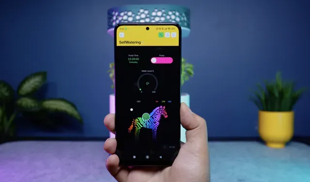
For the control side I created a simple app using a free drag and drop tool. It shows the water level, controls the RGB LED, lets me set pump schedules, and even allows manual start and stop for watering.
This step covers everything end-to-end: create a Blynk template and datastreams, flash the firmware, understand what each part of the code does, and build the mobile dashboard. It matches the pins and virtual pins used in the sketch: V1 = Pump (Switch), V2 = Water level gauge, V4 = Timer Input, V3/V5/V6 = RGB (zeRGBa Advanced).
0.2mm layer, 2 walls, 15% infill






Названия используются только для указания источника результата. Polyzon не аффилирован с перечисленными площадками.