
Бесплатно 
Battery Adapter CR2032 to CR2450 (configurable)
Thingiverse
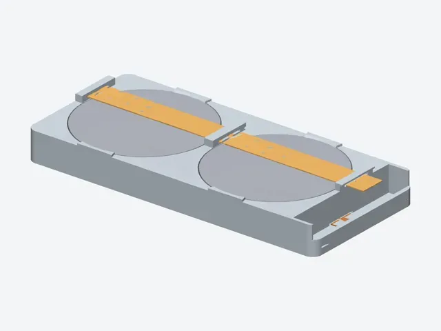
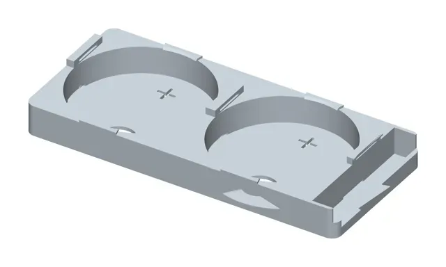
2× CR2450 in parallel → 3 V, ~1200–1250 mAh, in a holder only 6.98 mm tall. No soldering anywhere near the cells — the contacts are two identical strips cut from 0.13 mm copper shim.
I designed this as a drop-in power pack for 2.13" e-ink shelf labels (Hema / Alibaba HINK-E0213A41), but it is a standalone holder: anything that needs 3 V with double the runtime of a single coin cell can use it.
The problem I was trying to solve
I wanted to run a 2.13" e-ink price tag for as long as possible. One CR2450 gives ~620 mAh. Two in parallel double that without changing the voltage — the board still sees 3 V. Every approach I tried first had a real flaw:
Soldering directly to the cells kills them. The heat cooks the internal separator. Even when the cell survives, capacity drops and the seal can leak later. Tab-welded cells need a spot welder most people don't own.
Off-the-shelf clamshell holders are too tall. Commercial 2×CR2032 holders are 9–11 mm. I had 7.6 mm of depth to work with. Nothing fit.
Coin cells short out very easily on the top face. This is the part that trips most people up: on a CR2450 the crimped metal rim all around the top edge is the POSITIVE terminal . Only the flat disc in the middle is negative. Lay a flat strip across the top and it touches both — dead short. Most DIY holders I looked at ignore this.
So I designed one from scratch around those three constraints.
How the 0.13 mm copper contacts work
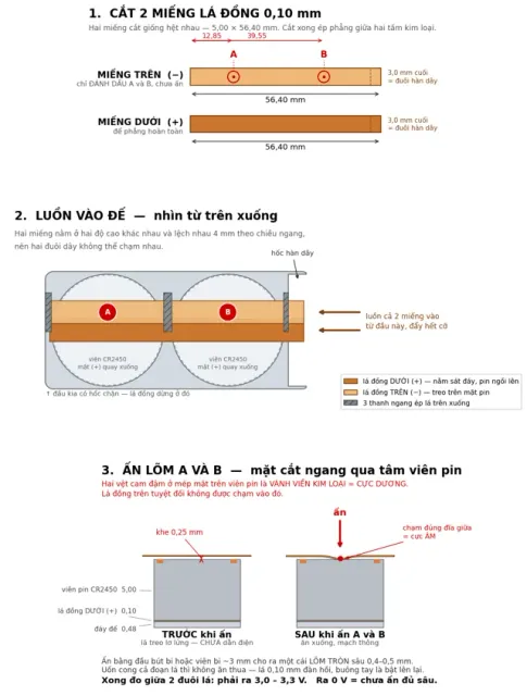
Two identical rectangles cut from 0.13 mm copper shim : 5.00 × 56.40 mm . Copper shim cuts with ordinary scissors at this thickness. A 1:1 cutting template PDF is included in the guides zip.
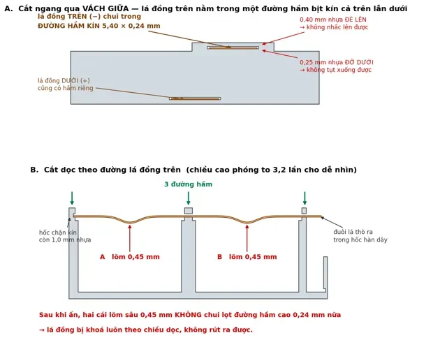
- Bottom strip (+) — lies flat on the floor. Both cells sit directly on top of it, printed face (+) down. That is the positive connection, and the weight of the cell makes it. - Top strip (−) — threads through three closed tunnels , 5.40 × 0.40 mm, moulded into the two end walls and the centre rib. Each tunnel has 0.60 mm of plastic above the strip and 0.25 mm below, so the strip is trapped: it cannot lift, cannot sag, and cannot touch anything by accident. The anti-short trick: the tunnels sit 0.25 mm above the top face of the cells . Once threaded, the strip hangs in mid-air over both cells — measure across the two tails and you get 0 V. It is not connected yet, and it physically cannot reach the positive rim.
Then you press two dimples into it, at the two marked points A and B, right over the centre of each cell. A ballpoint pen tip or a ~3 mm ball bearing, pressed until you see a distinct round dimple about 0.4–0.5 mm deep. The cell itself is the depth stop, so you cannot overshoot. Only those two dimples reach the negative disc; everywhere else the strip is still floating.
Press a dimple, not a bend. 0.13 mm copper is springy. If you just push the strip down over a long span it flexes elastically and pops straight back up when you let go. A small, sharply localised dimple deforms plastically and stays. This is the single step people get wrong.
Bonus: once the dimples are formed they are 0.45 mm deep and no longer fit back through the 0.40 mm tunnels — the strip locks itself in place and can't slide out.
Then measure between the two tails: 3.0–3.3 V . Solder your wires to the tails, which sit in an open well at one end, well away from the cells.
Parallel wiring rule: both cells must be the same type, same batch, both fresh. Check they are within 0.05 V of each other before assembly. A fresh cell paired with a used one will dump current into the weak one — it gets warm and both die early.
Widening the rear cavity of a 2.13" e-ink tag case
If you are using this inside a printed e-ink tag enclosure rather than standalone, two things matter.
1. The rear cavity has to be widened. A typical 2×CR2032 case has a cavity around 25.6 mm wide. A CR2450 is 24.5 mm, so a holder with side walls simply will not go in — there is barely 1 mm left for two walls. I widened the cavity to 26.60 mm , which leaves the holder 0.60 mm walls and still keeps 1.00 mm of plastic at the thinnest point of the snap rim that the front cover grips.
Widening it uniformly through the full depth matters. My first attempt only widened the lower part to preserve the rim — but the cavity mouth was still 25.6 mm, so the holder could not be dropped in at all. It has to be a straight prism, top to bottom.
2. The tall parts on the back of the e-ink board. On the HINK-E0213A41 board the JST battery connector (~2.9 mm) and the switching inductor (~3 mm) both stand on the face pointing at the battery. Everything else on that side is under 1 mm. Two consequences:
- The holder is built low on purpose: side walls stop exactly level with the top of the cells, and only three narrow 8.6 mm bars rise above that to carry the copper strip. Over ~69 % of the cavity the tallest thing is the cell itself. - The bars are offset to one side. Two mirrored versions (A and B) are included so you can put the bars on the opposite edge from the inductor, and turn the wire well toward the connector. With both printed you get four orientations to try. If it still fouls, add depth to the rear tray. Measure it rather than guessing: assemble everything, press the two halves together, and measure the gap left at the seam — that is exactly how much you need, plus 0.3 mm.
I am not redistributing anyone else's case. If your enclosure is someone else's model, do the cavity edit on your own copy. tray_widen.scad is included in the guides zip — it is an OpenSCAD script that takes your own STL as input and does the boolean for you. Nothing of the original is shipped here.
Print settings
- Material: PETG (PLA works; PETG holds up better near warm electronics) - Layer height: 0.20 mm — not optional - Walls: 2 | Infill: 20 % grid | Supports: none | Arachne: on - Both A and B on one A1 mini plate: 28 min 54 s, 6.48 g, 2.12 m of filament Every thin feature is an exact multiple of 0.20 mm: floor 0.60 (3 layers), copper tunnel 0.40 (2 layers), retaining lip 0.60 (3 layers). At 0.25 or 0.28 mm layers the slicer drops the tunnel and prints it solid — then the copper strip has nowhere to go. If you have to use a different layer height, edit strip_t / slot_slop / lip_t in the .scad and re-export.
Print flat, floor down. The tunnel roofs are 5.4 mm bridges — short, no supports needed.
Assembly
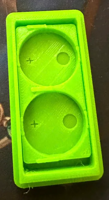
- Press the two cells into the pockets, printed face (+) DOWN . There is a + cut through the floor of each pocket as a reminder. Four tabs snap over them so they stay put. - Thread the bottom strip (+) into the low slot at the well end, push until it stops. - Thread the top strip (−) into the high rail at the same end, push until it stops. - Press dimples at A and B — 12.85 mm and 39.55 mm from the blind end of the strip. - Measure: 3.0–3.3 V. 0 V means the dimples aren't deep enough. - Solder wires to the two tails in the well. Grip each tail with tweezers between the joint and the body as a heat sink; 1–2 seconds with a pre-tinned iron. Two Ø6 mm holes in the floor let you push the cells back out when they're flat.
Specs
- Output: 3.0 V nominal, ~1200–1250 mAh - Size: 58.80 × 26.10 × 6.98 mm, one printed part - Contacts: 2 × copper shim 0.13 mm, 5.00 × 56.40 mm, identical - Cell pocket: Ø24.90 (CR2450 = Ø24.50) | anti-short clearance 0.25 mm above the cell face - Reusable — pull the strips, push the cells out, put new ones in Files
- CR2450x2_holder_v7_copper0.13_A.stl — print this one first - CR2450x2_holder_v7_copper0.13_B.stl — mirrored, copper rail on the other edge - cr2450x2_holder.scad — full parametric source - GUIDES-template-and-enclosure-script.zip — 1:1 copper cutting template PDF, assembly diagrams, and tray_widen.scad Everything is parametric. Using thicker copper? Change strip_t and every clearance recalculates.
Designed from scratch in OpenSCAD. Verified by boolean intersection tests: flat copper strip vs. cells = 0 mm³ (no short possible before you press the dimples), holder swept vertically vs. a 26.60 mm cavity = 0 mm³ (drops straight in), mesh watertight and a single body.
0.2mm layer, 2 walls, 20% infill Profile used for the photos: Bambu Lab A1 mini, 0.4 mm nozzle, PETG, 0.20 mm layer height, 2 walls, 20 % grid infill, no supports. Both mirrored parts A and B are on the plate: 28 min 54 s, 6.48 g, 2.12 m of filament.
The 0.20 mm layer height is not optional. The copper strip runs through three closed tunnels that are 0.40 mm tall — exactly 2 layers. At 0.25 or 0.28 mm the slicer cannot resolve them and prints them solid, and then the negative contact strip has nowhere to go. Floor 0.60 (3 layers) and retaining lip 0.60 (3 layers) are the same story.
Print flat, floor down, no supports. The tunnel roofs are 5.4 mm bridges — short enough that they come out clean.
PLA works too if that is what you have; I used PETG because the holder sits against electronics that get slightly warm.



Названия используются только для указания источника результата. Polyzon не аффилирован с перечисленными площадками.