
Бесплатно 
Snapmaker U1 — Chamber Exhaust Block (60mm fan, IKEALLER lid)
Printables
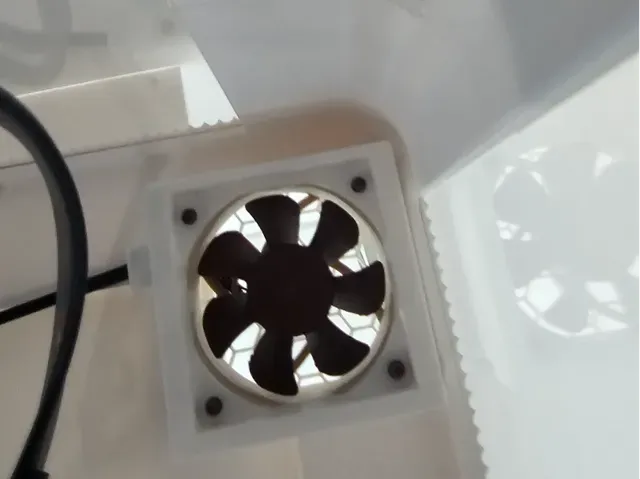
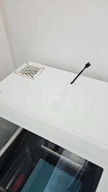
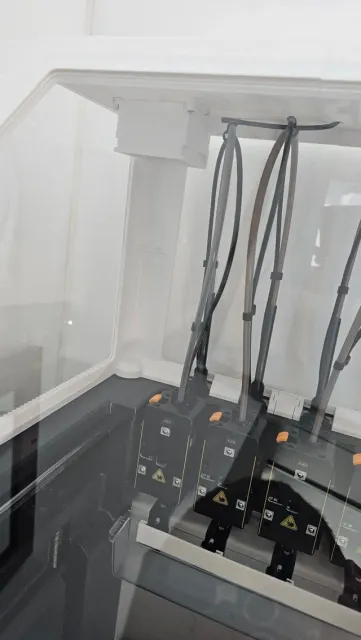
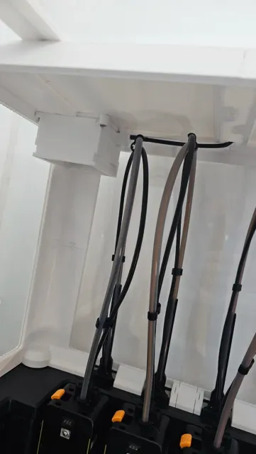
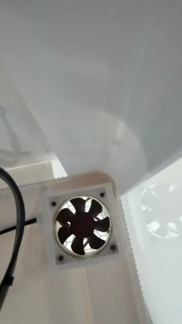
Okay, this is literally my first big design and all I previously did was mainly lunch box dividers or my backpack hook specifically measured to fit my desk curves.
I hope it is not very hard to replicate but fir sure it has a few things that are a part of the model development legacy. Sorry for that)
What I did:
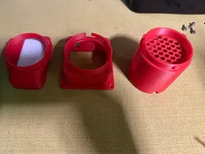
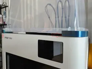
An active exhaust module for the IKEALLER / AMelo dome enclosure on the Snapmaker U1. It mounts to the printed top section of the lid, takes a 60×25mm fan, and pulls hot air out of the chamber.
A slide-in filter module is designed and will be added to this project once I've checked it against real filters. The mounting interface for it is already built into the block you're downloading.
Why
The U1's stock Cavity Fan only recirculates. It evens out the temperature across the chamber, which is useful, but the heat stays in the box. Once you seal the dome with magnets that starts to matter.
My baseline with the dome on but not yet fully sealed with stock bed:
- Chamber (cavity temp): 48–49°C on PETG - XY drivers: 91–95°C TMC2240 drivers top out around 105°C, so there isn't much headroom, and sealing the dome properly was only going to push both numbers up.
Design decisions
Filter sits before the fan. Air goes chamber → filter → fan → outside. The impeller stays clean, the filter muffles the fan so the noise stays inside the dome, and an axial fan copes with restriction better on the intake side than it does blowing into it.
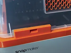
It mounts on the printed part of the lid, not the acrylic. And if you ruin a printed part you just print it again.
Two things to know before you start
You lose one magnet
The block sits in the top corner, and fitting it means giving up one of the dome's magnets at that spot. The dome still closes and seals properly, but it's better to know this now than halfway through assembly.
You probably shouldn't cut your lid
I cut mine with a Dremel cutting disk and it was a 20 minute job but for sure not a pleasant work at all. But reprinting the lid's top section with the opening already in the model is easier, cleaner and less risky. It's one part, and you get exact positioning instead of hoping your hole saw stays on the mark.
Just add a negative part 69x73 mm with longer edge going parallel to back wall of the hood. Also make sure to leave some space for the mounts.
If you do cut by hand: bi-metal hole saw, low RPM, no pressure, wood block underneath as backing. PETG doesn't crack like acrylic, it melts, so if you see strings pulling then slow down further.
Afterwards, glue a printed ring flange about 3–4mm tall around the cutout. A big flat panel with a Ø57 hole in it loses a lot of rigidity and puts all the stress on the cut edge. The flange fixes that and doubles as the seat for the block.
Bill of materials
Item Notes
Noctua NF-A6x25 5V PWM What I used. NF-A6x15 fits too if you want 10mm less height or whant to try to fit 2 of those.
M3 heat-set inserts × 3 you can also use regular nuts there I think. I aimed to have all 4 mounts with inserts but eventually had to use 1 nut.
M3 nut × 1 One mounting point has no room for an insert
M3 screws 13mm length at least
EPDM or TPU gasket strip Goes between block and lid. included in project models.
Dremel or a saw Only if you're cutting instead of reprinting
Printing
Print it in PETG. This sits in a hot chamber and PLA will sag.
I used Elegoo Rapid for the whole dome an this shell as well. 15 percent infill, 3 layers walls.
Model does need support. I used PLA interface layers (god I love this option in Snapmaker) and all went smooth.
The grille is 5mm octagons. Open enough that it costs almost no airflow, closed enough to keep my 8y.o son fingers out of the impeller.
Assembly
Three of the four mounting points take M3 heat-set inserts. The fourth one didn't have enough wall thickness for an insert, so it uses a plain nut in a captive pocket instead. Not the prettiest solution but it holds.
The Noctua's fan own rubber corner pads deal with the fan-to-block side.
Fan orientation: the open impeller faces the filter side and the hub with the wires faces out. Wires cutout is oden specifically for this setup.
Cable routing
I ran the fan cable through a relief channel in the centre of the top face, where it gets pressed against the lid during assembly. That's a compromise from cutting an existing lid. I stiill need to make a fitter on top to direct the wire to the back and ease to lid open.
If you're reprinting the lid section anyway, add a proper cable pass-through wherever suits your setup. It's much tidier. Nothing in the block depends on where the cable comes out.



Названия используются только для указания источника результата. Polyzon не аффилирован с перечисленными площадками.