
Бесплатно 
G90 Go Box (no power amp)
Thingiverse
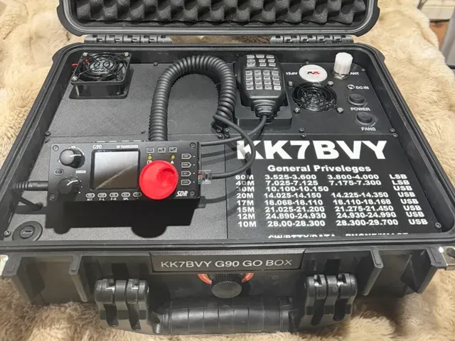
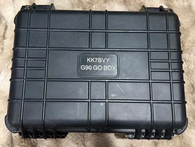
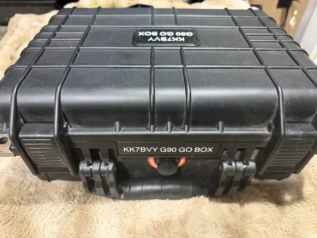
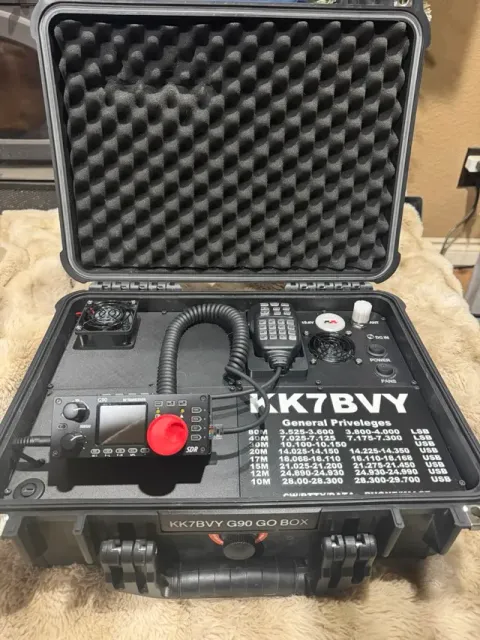
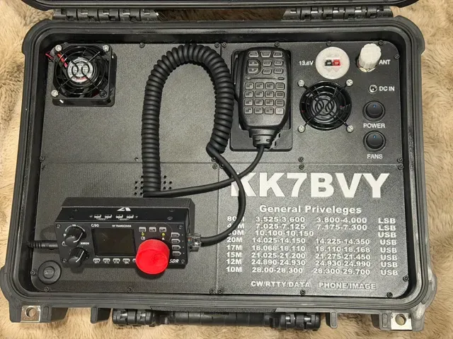
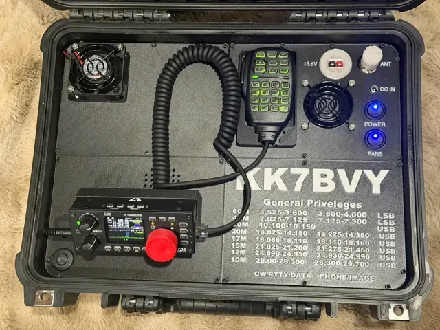
Wanted to give a big THANK YOU to Barbasr for sharing his design files for the Go Box he posted on Thingiverse. His wonderful design included the 125W Power Amp that Xiegu sells as an accessory. I don't own the power amp and strictly use my G90 for mobile operations like POTA, SOTA, WWFF, Field Day, etc., so I wanted to remove it from the design.
Bottom Left Half of Case
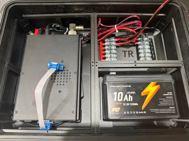
I kept the base bottom and top left exactly the same as Barbasr had them and placed the DE-19 below the radio base unit body. If you plan on using digital modes, you will need either the CE-19 or the DE-19 (DE highly recommended), along with a USB-C extension that I will link to below (along with all the other parts I used). To relocate the head unit, you will also need a DB-9 cable. I tried using the one that ships with the G90, but it was just too bulky to be usable. Amazon to the rescue! I also used a 90 degree SO-239 to PL-239 adapter to get the antenna port pointed towards the antenna connector on the case. Make sure you plug in the the data cable from the DE-19 to the back of the radio. As for power to the radio, I used the power cord that shipped with my G90 (I have the newer Anderson PowerPole connectors on the back of my radio) and just made up another cable that goes from PowerPole connectors to fork connectors. 16-Gauge wire was used for this.
Bottom Right Half of Case
The front of this half is taken up by the 10Ah battery. I modified the base section to have a recess for the particular battery that I purchased (link below) so that it could lay on its' side (which is the shorter dimension). This is really the only thing in this quarter of the case. I also used a piece of 3M VHB tape to make sure the battery doesn't move around. The top quarter on this side has two 6-position terminal blocks. One is red for positive and the other is black for negative. I incorporated two studs for each terminal block to set the block over in the case, the used 3M VHB tape between the studs to keep the block in place. This concludes the bottom of the case.
Top Left of Case
The top left of the case originally had a spot for the remote head unit for the power amp along with an Anderson PowerPole in the top left corner. I ended up blanking out this top piece (removed all holes) and added in holes for an exhaust fan here. Originally, my plan was to have it under-mounted, but the radio just took up too much space to be able to do that.
Bottom Left of Case
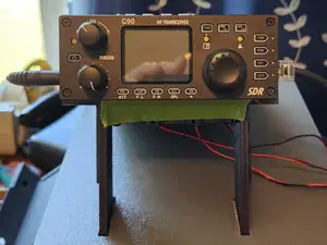
This area is where the remote head unit for the G90 lives. You just need to fish the DB9 cable through the mounting hole for the head unit and plug it into the back of the head unit. I did not use any screws and am just letting friction keep it in place. If it becomes an issue with the case being mobile, I will go back and add screws. There are two other holes in the quarter of the top; one for the audio cable to pass through from the DE-19 to the bottom jack on the left side of the head unit and another hole to mount the USB-C extension that you purchased from Amazon. This completes this corner of the box.
Top Right of Case
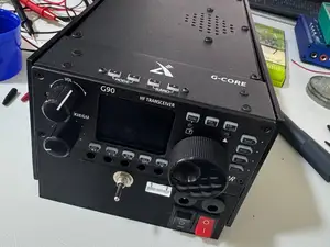
This is a busy spot! Here we have all the box controls mounted. From the top right, we have the SO-239 Bulkhead Adapter. This is just an SO-239 to SO-239 connector that is threaded with 2 nuts and 2 washers so you can mount it through something. To the left of that is a 3D printed PowerPole mount (files included) with a 3D printed nut on the backside. This is a great print and the PowerPole connectors fit into it nice and tight. There is also a hole through the connector (below the top, so cannot see in photos) if you want to run a piece of filament through to keep the PowerPoles from being able to move. Mine fit so tightly I did not even entertain using this, but it is there if you need it. I included this in case I needed to power anything else up (like maybe a VHF/UHF radio to use for spotting POTA). To the left of that is the mic holder. I modified this a bit from the original, dishing out the bottom a bit so the mic would fit a little more secure. I also ended up cutting off a corner at a 45 degree angle to allow for a little more clearance for the mic. I wish the dished out part was a bit smoother, but honestly that was just a visual issue and I didn't feel that going back and redesigning that part was worth the time it would take. Moving on....to the right of the mic and below the PP connector is the Intake Fan. This draws air into the case and exhausts it out on the left top portion. This puts part of the radio in the direct path of the airflow. If I was to design this again, I would probably move the battery to the top right corner of the case and move all the controls along with the intake fan to the bottom right corner of the case. This would allow for a corner to corner path for the air and probably better circulation and heat removal. You know what they say about Hindsight ! To the right of the fan (from top to bottom) we have the DC In port used to charge the battery. With the Power switch in the OFF position, this disconnects the battery from the terminal blocks so no power is sent back to any of the other electronics in the box while charging the battery. This is just a 5.5mm x 2.1mm jack. I recessed the hole a bit because the DC jacks I had on hand didn't have long enough threads to make it through the lid thickness and allow me to get a nut started. Recessing the jack into the lid helped solve that issue. Next switch down is the Power switch. This kills all the power between the battery and the terminal blocks. The switch below the Power switch is the Fan switch. This is used to turn the fans on and off. I am getting amazing airflow through the case with this Push/Pull configuration of the fans. Just make sure you look at the arrows on the side of the fan housing to make sure you are putting them in the correct way. I may end up adding a fan speed controller in the future if the noise of the fans blasting away on their highest speed becomes an issue.
Bottom Right of Case
Not much going on here. The battery is very close to touching the bottom of this lid piece, so it is kind of dead space. Rather than just have a blank space here, I chose to add my call sign as well as my band privileges (Yes, I realized I spelled Priveleges wrong on my go box! Doh! Reprint coming). I am a General Class Operator, so I just added the appropriate text that I wanted to reference in Bambu Studio while preparing the print.
Needed Parts:
Things you will need. I ordered these from Amazon, so those are the links that are provided. (As an Amazon Associate I earn from qualifying purchases.)
- Apache 3800 Case - DC Jacks - Round Switches - SO-239 Bulkhead Connectors - Terminal Blocks - Fans - Batteries (I bought 2, but you can just buy 1) - DB9 Extension Cable - M3 Screw Assortment - 3M VHB Tape - Elegoo PETG-CF filament - USB-C Bulkhead mount extension cable




Названия используются только для указания источника результата. Polyzon не аффилирован с перечисленными площадками.
Комментарии