
Бесплатно 
5 axis robot arm
MyMiniFactory



The rough plan:
A glove that tracks the movements of the hand and then sends it via WiFi to a Raspberry Pi, which runs a program that then displays a visualization and transmits the movements of the hand in real time.
Accurate execution:
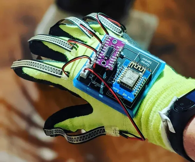
Our idea is to make it a glove that records the individual movements of the fingers, pitch and roll of the hand. This data is then sent to the Raspberry Pi/Laptop via the Wemos D1 Mini using a WiFi connection with TCP. In this connection, the Wemos D1 Mini is in AP mode i.e. it hosts its own WiFi network (as the school's network does not allow communication between the Raspberry Pi and Wemos). One advantage of this setup is that you can operate the glove where you want and are not tied to network connections. The collected data is processed by a Python script to send the correct signals to the individual servo motors of the arm to implement the movements. This involves converting the data from the gyro sensor directly on the Wemos D1 into position data, which is then sent to the Python script along with the movements of the individual fingers. This script then converts the position data into the positions of the individual servo motors, which are then controlled accordingly.
Division of labor:
I'm developing the hardware and the visualization in Unity.
My friend is developing software for the arm in Python, processing data from the gyroscope and interpreting it correctly, all other activities that have to do with the connection of glove and PC.
Progression:
We first considered how to capture finger movements so that we could use them as a reasonable control for gripping. An initially inexpensive solution for this appeared to be pressure sensors, which we can also manufacture ourselves and thus save ourselves the unnecessary expense of purchased sensor technology.
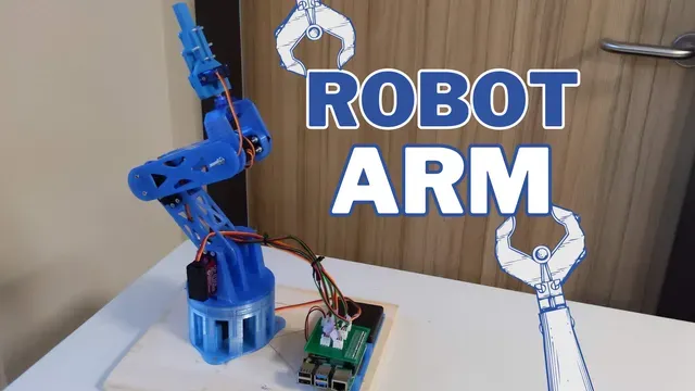
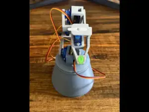
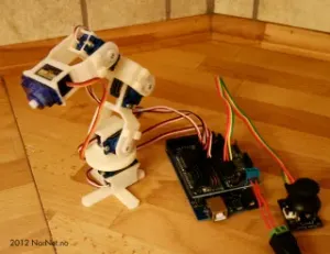
Next up was an arm to translate the movement of the hand. A small 3D printed robotic arm seemed practical for this, on which I can freely indulge my passion as a passionate 3D printer fan. The arm was small and quickly printed, but very limited in its range of motion. The arm consisted of two joints, which not only interfered with each other, making it difficult to calculate the optimal position of the servo motors to reach a point in space, but were also very limited in their radius. https://www.instructables.com/EEZYbotARM/
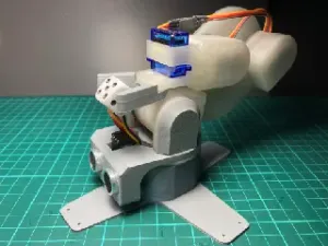
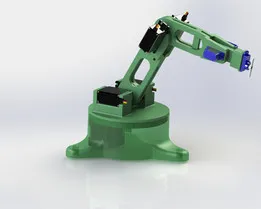
After we, or rather the 3D printing Nerd, had finished the arm, we noticed the considerable flaw of the arm, which not only had a very limited range of motion due to its design, but was also very inaccurate and weak due to the use of cheap servos. We then decided on a version with larger servos and more freedom of movement (https://www.instructables.com/3D-Printed-ROBOTIC-ARM/). This was now a bit stronger and we additionally decided to develop a circuit board.
As a result, we had difficulty working together on our project due to the lockdown. We fixed this problem by setting up digital access to the Raspberry PI via a VNC client and a webcam, which enabled the programmer to control and see the arm from his home.
Parallel to the robot arm, we always worked on the glove for controlling the arm. Now that we knew the robot arm was working and we only had to work on the glove, the 3D printing Nerd designed PCBs (Printed Circuit Board) for the glove with Wemos, gyroscope sensor, multiplexer, pressure sensors and a header board for the Raspberry Pi to control the servo motors. We ordered these from JLCPCB.
For the Raspberry Pi and the battery, which we need because the Raspberry Pi does not provide enough amps, the 3d printing Nerd printed a holder. With this one, we made sure that you can use it again and again without breaking it. There are, for example, melted metal threads, so that the screws are always easy to remove, precisely adapted shapes of the battery, that you can simply press the battery box in and everything holds.
Then the boards arrived and there were minor problems with the layout of the paths on the board, resulting in a reorder. The board for the Wemos D1 Mini had the problem that the multiplexer in the designer tool of EasyEDA didn't have the same position for the pins (The multiplexer is the purple board on the picture). At first we tried to solder a PCB over which the multiplexer can be plugged in; but because the displacement was so big, there was not enough space on a breadboard to move everything around. Thus we decided to work around the problem with simple jumper wires that are soldered to the multiplexer.
When we connected the board for the robot, we realized that the design we had used so far was very poor. The arm was in a tilted position all the time, so the motor was very heavily loaded all the time. These motors were also not really high quality and only held a maximum of 10kg. We saw this when the lowest motor broke, because almost all the gears in the servo broke off. That made us think about designing our own robot arm with Inventor. In addition, the robot arm was not very stable and wobbled a lot when you used it.It also had a general tilt to the right side, which made controlling it a lot more difficult.
After 2 weeks of trying to build reliable pressure sensors ourselves and only got meager results, where the sensors could distinguish just three positions. We decided to order 5 pressure sensors for the glove. For the glove, we printed a holder for the circuit board that is adapted to the slight curvature of the back of the hand. Because of the circuit board, we only need a 10kOhm resistor in the circuit to read all the data from the flex sensors. A small disadvantage of having all flex sensors connected to one circuit is that you have a small error of 15Ohm per sensor that is bent. But this is only a small error, because our data range goes from 0 to 1024 i.e. if all but one finger is bent the error would only be 60 ohms or 5.8%.
The first hurdle for the new robot arm was to develop a stable base, since the original base was mounted directly on the servo. For this we then developed an axial bearing with softair balls. We had slight difficulties with the design, since it was generally the first ball bearing that we designed. The first idea was to drive the thrust bearing with a smaller gear, but there is a small error in thinking: you lose distance when you transfer power from a smaller to a larger gear, and since you have a limited radius with a servo, we ended up driving the thrust bearing directly with the servo. We also had problems with the yellow softair balls because their tolerances were too small, which caused the thrust bearing to get stuck all the time.
Left old substructure & right thrust bearing
With this posture, it was important to us that the robot arm with the axis rests on two ball bearings and is in any case more massive than the original part.
With the original arm there were no fixed axes i.e. all axes were just plugged on top of each other without protecting the other parts from slipping out. Another advantage is that here we could put the cables directly through the body. Instead of relying on long threaded rods like the original, we directly developed solid parts that you 3D print and then just glue into a hole. These parts will never leave their position because the shape for each of the four holding points is a trapezoid.
Now that we had finished the design, we realized once again too late that the servo at the lowest point is probably much too weak to lift the whole arm. That's why we then decided to order a new, stronger servo with 20kg of power so that we don't destroy a second servo. The new servo even has an aluminum arm to transmit the force, but the screws didn't really hold, so we had to fix it with hot glue.
With our glove we still had the problem that we had no power, so we have a small powerbank holder designed which one makes tight with textile rubbers. This can be adjusted to the thickness of the upper arm and is also very easy to remove, because you have two small openers in the middle. In the power supply, we have but again replaced the power bank, because the old was no longer to charge.
The last step is just to turn the data from the glove into lessable signals. These are then sent to the Raspberry Pi, which interprets them and takes coordinates. We also created a Unity project to show the finger and hand movement and the first thing we had to did is the middle finger 😅.
Result:
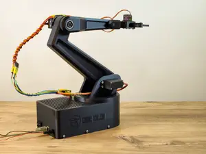
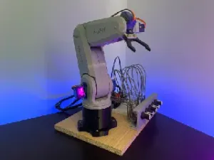
In the end, we can say that we have developed a pretty cool looking robot arm. The only problem is that it's not really the best at being a robot. It is quite limited in its carrying capacity. The movements look very good and it's not as limited as the other robot arms. We had a lot of fun developing the robot arm and I can say that I learned a lot from it.
Difficulties:
- The idea is that a position in space is calculated by the data from the gyro sensor. This position is then passed to the Raspberry, which then has to move the arm so that it is at the position in space. So the arm should correspond to the movement of the own hand. In order for the arm to really be in the position where it is supposed to be, it has to move every single joint correctly. Since the arm has four axes, but is in a 3D space, there are infinite possibilities to reach this position. Furthermore, there is the restriction of only 180° per axis, so the calculation of the optimal position for each axis was very complex. Therefore it is advantageous to implement an algorithm, which automatically finds a good optimum of the position. The whole thing is called Gradient Descent. The idea is to perform a curve analysis of the difference function, which represents the difference of the current position to the desired one. A minimum is then searched for. This minimum represents a minimum difference of the momentary position of the arm to desired. Therefore, if the difference function is at a minimum, the arm is close to the optimal position. - The first robot arm was too small, had no force, was too inaccurate and had a limited range of motion. We solved this by building a larger arm with stronger servos with more accuracy. - The second robot arm definitely had more power, was more accurate and had much more room to move, but was still too wobbly for us. - Development of an axial bearing without prior knowledge - In the beginning we used the yellow softair balls, but this led to the fact that the bearing could not really be turned cleanly, because these balls have a lot of unevenness. We then got professional bullets with the same size in the softair range. Our final solution in the event that the new bullets would not have made a difference, to use Ballistol. It's a natural lubricant that doesn't break down plastic like WD-40. We didn't need it, though, because the new balls were running so well that we didn't want to change anything on them. - Another problem was that Max forgot that transferring power from a small gear to a large gear reduces travel a lot. Solution was then simply to attach the servo directly to the thrust bearing. - The lowest servo destroyed itself, because the arm was too much for it and all the gears in the servo gearbox were torn off. So we bought a new stronger servo with 20 kg power and designed a new base to fit it. - With the glove there were problems, because the Wemos D1 Mini has only one analog pin but we wanted to read 5 different analog signals, that meant for us that we had to connect a multiplexer. This can switch between the different analog signals. This had the advantage that we had to solder only one resistor, because the signal of the sensors always comes out at the same place, even if we change the input. - At the battery box the connection had a loose contact, because Max probably attached it only to 90% cleanly, whereby the servos got no more current. But we thought it was because of the board, went to Max to get a new board and when we were back we noticed that it was because of the power supply. - Calculating the hand in space with only data from the gyroscope turned out to be more difficult than expected. The gyroscope sensor gives us data about the force acting on it at the moment and the movement in degrees around each axis. If weneed to derive a position in space from this data, we have to integrate the force to get acceleration, and then integrate it again to get the position. As a result, measurement errors have a significant impact on the final position because they are integrated twice. The data from the gyroscope has an approximate measurement error of about 5%, which makes the whole approach of the calculation impossible. Even expensive gyroscopes are not able to determine an exact position from collected data. Therefore, the only solution to our problem is to make the control of the arm via gestures instead of mimicking the movement of the arm. Program:
inverse kinematik software robotarm
Kostes:
5 * Servos (10kg) -- >24.42€
Servo (20kg) -- >17.66€
Filament -- >around 30€
Glove -- >2.99€
Kabel -- >12.00€
PCB -- >27.44€
Wemos D1 Mini -- >3.25€
Multiplexer -- >1.73€
Rundmuttern -- >2.50€
Gyro(MPU 6550) -- >1.05€


Названия используются только для указания источника результата. Polyzon не аффилирован с перечисленными площадками.