
Бесплатно 
270 Degree Geared Hinges (V2) for K1/K1 Max/K1C. Easy print option. Not print in place.
Printables


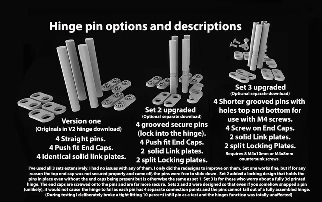
Update November 1st 2024:- added some fatter link/connectors. Originals (by design) were thinner to allow the pins to be seen and also guarantee no sanding/post processing would be needed with an out of spec print. Newer fat links are labelled as ‘Fat’. Stl files supplied are in pairs, they are
‘fat upper slot links’ for the upper slot of both hinges
‘fat lower slot links’ for the lower slot for those using the non groove pins
‘Fat lower slot clips’ for the locking pin type lower slots
Update:- 4th October 2024 :- Added a pin that has no safety groove/clip function. It is instead, a solid pin (with holes top and bottom for screws) without the groove for those who may prefer it. Somebody rated this set four stars instead of five, likely as they felt the groove was superfluous, hence this addition. If using this pin you will need to print an extra pair of solid links instead of the split clips. I have not test printed this new pin but I can't see any potential for issues as it predominantly shares the same dimensions as the grooved version. Personally I see the non grooved version as a step backwards, but the option of pins without it is there for those who may prefer it.
Description:-
Optional screw versions of the hinge pins for my 270 degree hinges. These Pins will fit both version 2 and version 3 of my hinge sets (they also fit the now deleted version 1 as well).
PETG ASA PLA .4 nozzle .2 layer
When I remixed a 270 degree hinge for the K1 Series I had a number of things in mind. Crucially I made sure that if any part of the hinge failed in a bad print, there would be some kind of backup. All my 270 degree hinges use the top and bottom plates of the hinge as the primary parts that hold the hinge gears meshed together correctly. The central upper link does it's part as well (and acts as a backup), with the clip below it then making sure the pin cannot fall out of the bottom when the end cap is not fitted. Plenty of redundancy. I aimed for a design that would still keep the hinge working fine even if you had accidentally printed a weak part. A broken connection, even a snapped pin, would not cause a catastrophic hinge failure. At worst a component failure could potentially introduce a door sag that you would feel (or see) immediately and be able to quickly rectify without any risk to the glass door.
I had originally avoided releasing my version that used screws as I was trying to keep the hinge fully printable, but I am adding it now as I have been asked a couple of times about a screw together option (Edit, I've also now seen a remix that sacrificed some of the safety redundancy). To that end, these pins are the strongest version of any to date. Short of running a solid steel pin top to bottom in the hinge I think this is the best option.
These pins are shorter than any previous versions I have released. When fitted they stand just proud of the hinge. Personally, I printed my test pieces of the pins in PETG as it is a stronger option for cutting a thread with an M4 screw.
To use these pins you will need eight M4x10 screws (countersunk). M4x8mm will also work. If using regular (non countersink) button screws you may be able to flip the plates over but I haven't tested that possibility and if you do that you need to make sure not to overtighten the end caps.
The pins are based on my modified pin set with the securing clip (to be fitted in the lower slot of the gears) preventing the pins dropping through if there is no top end cap fitted. The clip still serves that same purpose here. The pins should rotate around in the clip when fitted. If it is too tight it may be forced off the pins when the hinge is opened. Make sure when first using the hinge that this clip stays in place. If it does push free? remove the clip and enlarge the hole a little with sandpaper or a sharp knife. Of the 6 sets I printed, only one individual part suffered from being too tight. Given that this set uses screws to hold the pins in place, the groove option may be overkill for some users and you may not want that option, if so there is now a straight pin variant added to the downloads without the groove that uses a full link instead of the split link in the lower slot.
All 4 pins pins have a 3.6 x 10mm hole in each end. Using one of the screws you can easily cut a thread into the pins at both ends using the screw itself (or for those with a tap and die set you can cut the thread easier using that option). You may need to open up the start of the hole a small amount to get the thread to grip so it can cut as you screw it in. I suggest doing this Before fitting the hinges as with PETG it took some force to cut that thread. Do it by a half turn forward and a quarter turn back. When it get's too tight, back it out a little before going back in and repeating until you know you have cut enough thread for your screws. If you print the pins in PLA, take extra care while cutting the thread as it would be all too easy to snap the pin if you rush it.
I prefer the look of the printed push fit to the screw version, but will concede that the screws are the stronger connection and remove any potential concerns of an end cap ever coming loose.
I opted for countersunk screws as it means that apart from where the screw threads touch the print inside the pin itself, the threads do not contact the end caps. Only the countersunk portion is in contact. If for any reason a pin is too tight in the hinge and it is forced to turn while the hinge is opening or closing? The chamfer of the screw head will massively minimise any wear at the end caps.
I've used two methods for fitting the hinges, both are described separately on the version 2 and version 3 270 degree hinge pages.
To assemble the hinges with these pins. Cut the threads in the pins first, you will likely need two Allen keys/Hex wrenches for this as they get tight fast. 10mm is in reality, overkill, 8mm would be fine, and in a pinch, maybe 6mm, but I designed them for maximum metalwork in the pin without weakening the pins.
Make sure the pins rotate cleanly in the hinge holes. If for any reason they are tight, either run an 8mm drill bit through the hinge portions or sand the pins until they move freely.
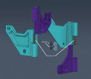
The groove of the pins should be aligned with the lowest slot of the gears when fitted. As you slide the first pin through, catch the ‘link’ in the upper slot and push the pin fully home. Align the 2 hinge pieces as straight as possible and slide the second pin in, again catching the link and pushing it fully home. Don't fit the clip yet. Take an end cap and screw it on either the top or bottom, it doesn't need to be fully tightened yet. It is possible to misalign the gears while doing this but there is enough play to re-align at this stage.
Fit the other end cap and start screwing it down. Only fully tighten the end caps when you are happy the alignment is correct. Once fully tightened, add the retainer clip, push it firmly until it clicks home.
You don't need to over tighten the ends caps. Just enough to be snug is all that is needed.
Do the same for the second hinge and that's it finished.
Instructions for fixing them to the printer is on my V2 and V3 270 degree hinge pages.
I printed the pins and end caps in PETG at 60 percent infill. Because you will be cutting a thread into the pins, don't be tempted to go for a low infill setting.
The end caps are a quick print so you could go even higher with the infill without losing a lot of time.
Note:- Personally I prefer to fit the hinges to the printer while separated into their two halves. After printing I do a full hinge build and test to get them ready, then remove a pin from each hinge. Tape the door in place on the printer, Fit the hinge pieces loosely in place on the door and printer (snug but movable). Only then do I reconnect the hinge halves together. This for me has proven to be the best option as it removes any potential misalignment of the gears as the hinge halves are connected. Although more fiddly with the screw pins it is still my preferred fitting choice.
I would suggest PETG as the filament of choice for these pins as cutting the thread was deliberately made to be tight. PLA may also work fine but could fail when cutting the threads so be prepared for that possibility with PLA. Once screwed together and fitted to the hinges they should be every bit as good as PETG in actual use.





Названия используются только для указания источника результата. Polyzon не аффилирован с перечисленными площадками.