
Бесплатно 
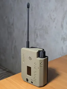
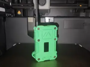
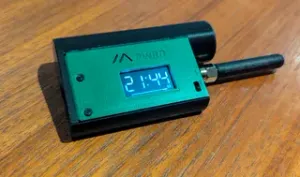
Heltec LoRa32 V3 Meshtastic Case with Encoder/Buzzer/GPS/Environment sensor, M5Stack CardKB Keyboard-ready
Printables
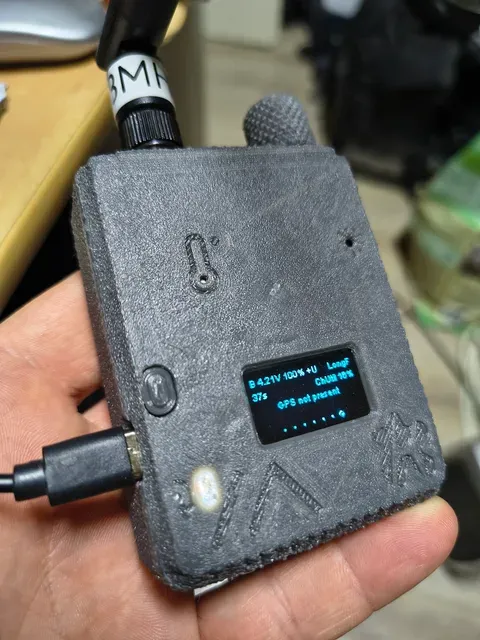
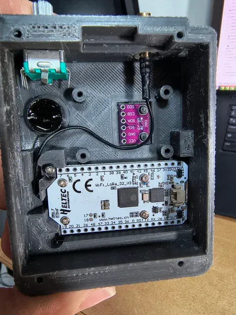
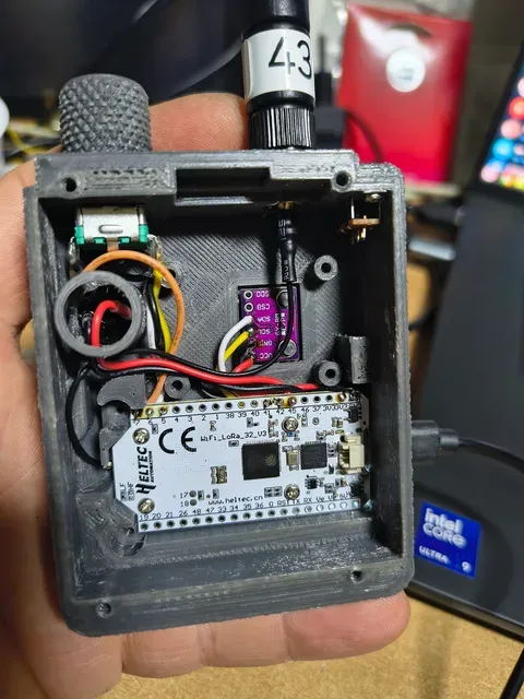

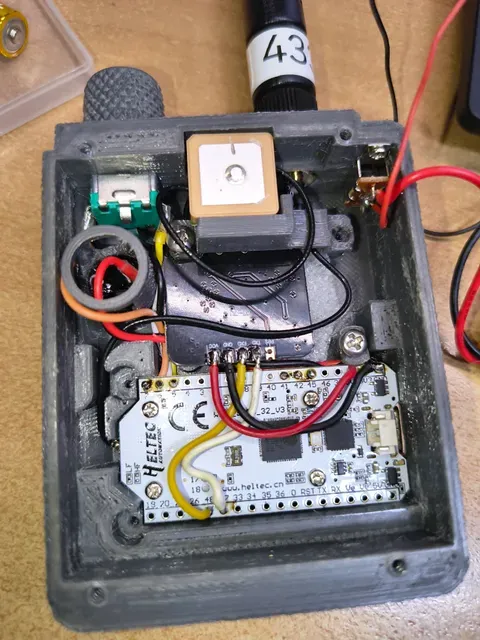

Case for Heltec WiFi LoRa 32 V3
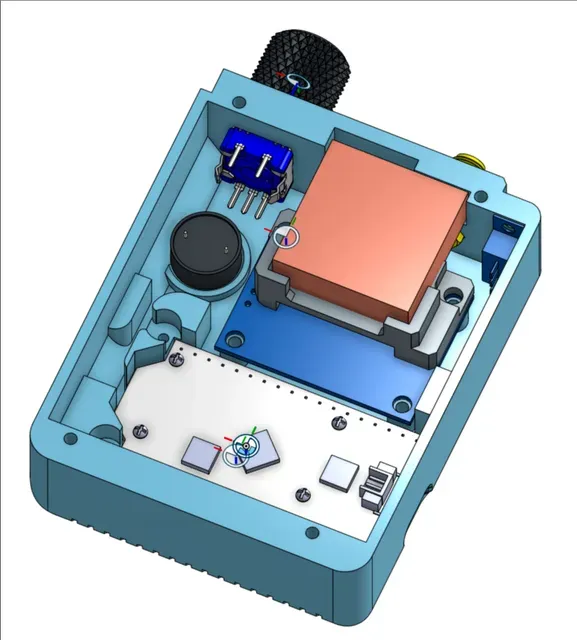
This case is designed for the Heltec WiFi LoRa 32 V3 and includes the following components:
Included Components:
- GPS Module (NEO-6M or GT-U7)
- On/Off Switch (S3P = SRS3P, 19.4 x 5.6 x 5mm) → Link
- GY-BME280 Sensor
- 3000mAh Battery (974058)
- Buzzer (12mm)
- EC11 Rotary Encoder
Screws Required:
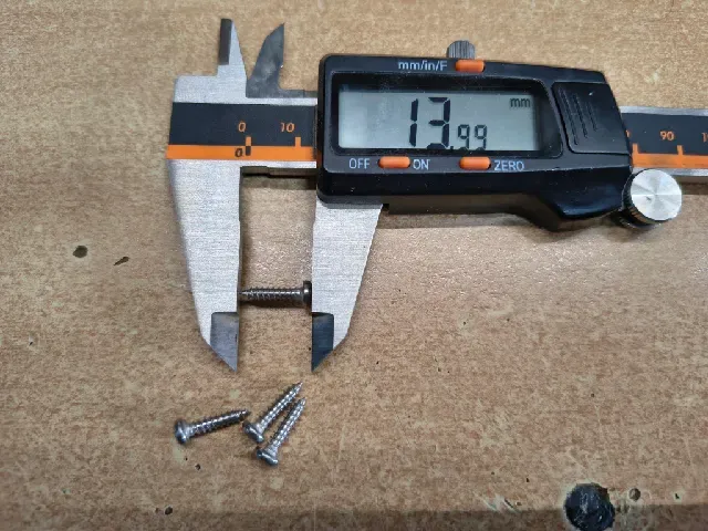
- 4x M3 × 12mm (thread length) sheet metal screws → for fastening the back cover
- 2x M2 × 4mm sheet metal screws → fastening the switch (same as the ones fastening the Heltec display)
- 2x M2 × 4mm sheet metal screws → fastening the heltec board (same as the ones fastening the Heltec display)
- 2x M3 x 6mm (thread length) sheet metal screws → fastening the GPS module
- 2x M3 x 8mm (thread length) sheet metal screws → fastening the GPS module with the GPS antenna holder
Assembly Instructions:
Install the switch
- Place the switch as shown in the photo.
- Use an M2 screw (same as the Heltec display fastening screw) to secure it.
Install the EC11 Rotary Encoder and Buzzer
- First, insert the EC11 rotary encoder.
- Then, place the buzzer into its slot.
- Secure the buzzer using the buzzer fastener—this will be held in place by the back cover.
- If the buzzer fastener is too high, use sandpaper to adjust its height.
Install the GY-BME280 Sensor
- Place the sensor into its designated slot.
- Melt the two small cylinder heads with a soldering iron to fasten it.
- Optionally, cut a small piece of foam to cover the sensor from the inside, protecting it from internal heat.
Mount the Heltec Board
- Use a washer and an M2 screw (same type as the Heltec display screws) to secure the board.
Install the SMA connetor
- put the SMA connector to is place, wasten the screw
- it us practial to put a rubber washer between the antenna and the SMA connector when the antenna is screwed into its place to secure it
Install GPS control board
- Put the control board into its place
- Put the GPS antenna holder on the GPS control board, and fasten the screws
Wiring:
Configuration changes:
Enable canned messages in android:
Enable buzzer:





Названия используются только для указания источника результата. Polyzon не аффилирован с перечисленными площадками.