
Бесплатно 
18650 single cell power bank
Printables
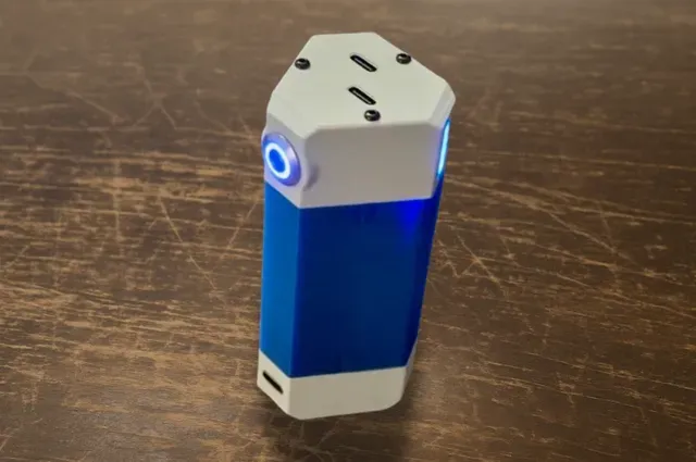
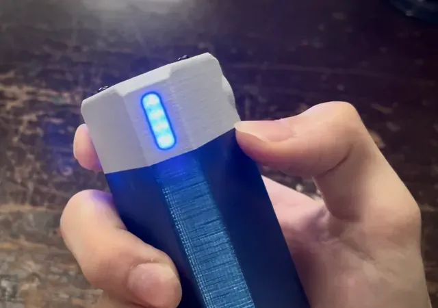


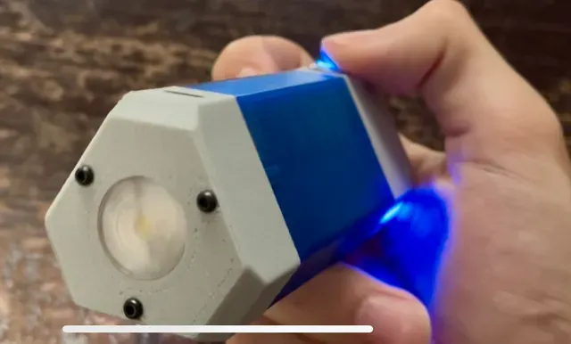


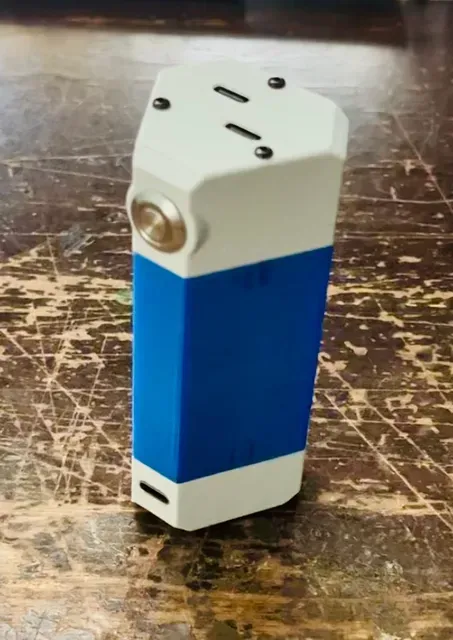


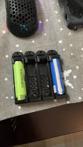
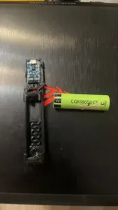
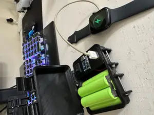
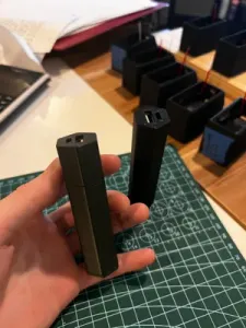
Maybe it's just me, but for how integral to modern life our portable devices are, don't our power banks just lack the pizzaz to match? I felt that way, so I designed my dream power bank, and dubbed it the trinity power cell. It runs on three 18650 batteries and is designed to fit two 3.1 amp smart charging modules, and can serve as a flashlight too.
Before you proceed:
This is not what I'd call a project for a beginner. It requires a good deal of wiring in a tight space, and soldering to crowded and small pads. You should choose whether to proceed based on your confidence in the the following skills.
- precise soldering - using a hot air tool - wiring in tight spaces - rules of electrical circuitry Of course, I will try to make everything as clear as possible for you guys, and that includes the visual instructions and parts list that are included with the project photos. They're all the way in the end, you will find them.
Notes about the materials
- For a FULL materials list, refer to the images of this project's page. The list does not include wires, because most people who want to do this project will likely have them already. That said… - Normal silicone wire tends to be too thick and you may run into trouble fitting every bit of wire in if you use silicone. Instead, use FEP Teflon wire of 24AWG for battery connections, and 28AWG for everything else. - A budget option for wire is actually the stranded wire inside ethernet cables, if you have some old ones lying around, cut them open mercilessly for the conductive gold within, as I did. Just be careful because they are PVC and can melt from say, an errant touch with a soldering iron. - Why do I recommend UV resin? There are some connections in the project that are frail due to their small size. I have found UV resin to be a powerful and versatile stabilizing agent for solder points. Also, it can be used to protect wires from being sliced by nickel strip if you choose to spot weld your battery back. - Since the original color of the charge module's charge indication LEDs is blue, you can only replace them with LEDs that run at a similar voltage, like white, green, pink, or blue, or risk burning them.
And now, the instructions:
- Print all the parts for your chosen version. Parts that absolutely must be transparent are the LED lens and the charge indicator windows. PLA is not recommended because the charge modules and LED may get hot enough to soften it. - Prepare the parts that need heat insert nuts. - 6x M2x4 for the main case, 3 on each side - 3x M2x4 for the LED bracket in bottom cap - Lastly, 4x M1.6 for the inside of the top cap - Prepare your battery pack - (in parallel) either solder or spot weld them in a tight triangular formation, making sure to leave the small center gap formed by putting the three batteries together unobstructed by wire or sharp edges of nickel strip. This gap will later serve as a wire conduit. - Prepare the charger module as shown in the graphics. Essentially, you have three main goals - 1, to connect the inputs of the modules in parallel so that they can both be powered from the battery (and charged simultaneously too). 2, to solder on wires for the button switch so that the modules can be activated, as well as wires to power said button's ring LED. And 3, to replace the SMD battery status LEDs on the modules with pre-wired SMD LEDs, so that you can extend them to the charge windows. It is important to read every bit of detail in the graphics to get this right. - If you look at the CAD, you'll see there is 3mm of space between the charging modules. Make use of this space wisely. I used it to connect the module battery inputs together. - When you solder on the prewired LEDs, make sure to pay close attention to the polarity, follow the graphic. When done, plug it in for a quick test, and seal the solder points with just a touch of UV resin for better strength. - The next step is to glue the LED ends of the prewired LEDs into the charge windows. It is very important to get the order correct, meaning first LED goes in the first hole, second in the second, and so on. I recommend using UV resin for this step because it can fill the holes and transmit the LED light nicely but superglue works too, you just need to figure out how to keep the LEDs still as it dries. I did mine with resin and held them down with a toothpick with one hand and shined the UV light with the other. - All these LEDs make quite a bundle, so you can give them a few twists as a final touch for organization - So now the modules should be connected together, both their battery inputs and their 5v inputs. They should also have wires for the button and the charge indicator LEDs. You can now carefully slot the two modules into their place in the top cap. You can refer to the CAD for this step, which does include models of the charge modules. Once they're nicely seated, you may gently slide the charge windows into their ports, and thread all the wires for the button out the button hole. - The top cap has thin slots meant to accept the thin tabs of the charge windows. - Mind the orientation of the charge windows, so the LED that indicates 100% charge is at the top, aka nearest to the USBC outputs of the module. - You can combine button wires of both modules in parallel, just as with the inputs - Using 4x M1.6x5 screws, screw down the charge module bracket onto your assembly. This will have the affect of stabilizing it. It will also retain the tabs of the charge windows from the top, securing them as well. - Solder the button wires to the button, with reference to the instruction graphics. To make sure you've done it correctly, temporarily connect the battery to the charger modules and give the button a press. The button's ring LED and the charge windows should both light up. Wait 30 seconds, and if the whole thing shuts down, you've done it right. You can push the button flush against its hole, and glue it in place with a few drops of glue. I recommend some light clamping to keep it in place is it dries. - At this point, all that remains for the electrical assembly is soldering a connection to the battery, and making the LED circuit if you opted for the LED version. - Notes on the LED circuit: The LED circuit is composed of a long press trigger module, a constant current driver, and the LED itself. It requires three input wires, a positive, a GND, and a signal for the trigger module. As shown in the graphics, this signal is switched by the button, from the same wire that activates the charge modules. - Whichever way you mount the battery, one of the poles will be easily available for the LED circuit, while the other will have to be run down through the center, as will the signal wire for the trigger module. - The electrical and mechanical assembly for the LED are intertwined in a sort. first, lower the lens into place in the bottom cap. Then place the LED with wires already soldered on (no longer than 6cm). Next, tightly secure that whole subassembly using the LED bracket and the 3x M2x5 screws. Lastly, glue in the female USBC connector with its pads facing up so they can be soldered later. - Finally, with all the electronical connections made, you may begin the physical assembly of the parts. The top cap connects to the main case with 3x M2x30 screws. The bottom cap attaches to the other side of the case with 3x M2x25 screws, or 3x M2x12 screws if it is the no LED version. Ok, so admittedly this project is far from simple. I tried to keep the instructions short and ended up typing an essay. So truly you are the g.o.a.t if you've managed to get this working as intended. But if it is too complex, remember, you have access to the STEP files! You can modify this project to make it more simply or assembly less troublesome. And of course, I'll be here, ready to answer your questions.






Названия используются только для указания источника результата. Polyzon не аффилирован с перечисленными площадками.