
Бесплатно 
Filament Sensor (Endstop switch) Vz-HextrudORT PLUS
Printables




Updates:
- 2026-03-31
- Added step of PCB mockup (Luke's USB Cam.step)
- 2025-06-27
- Added center hole to extrusion mount for potential pivot joint on a secondary mount, renamed it to Hinge Mount
When I got my camera module, I noticed that the holes did not line up with the board, and they seemed to be sized for larger fasteners/odd lengths. For a while, I wasn't using the cam, or using the lid of my VZ330 to kind of hold the cable in place.
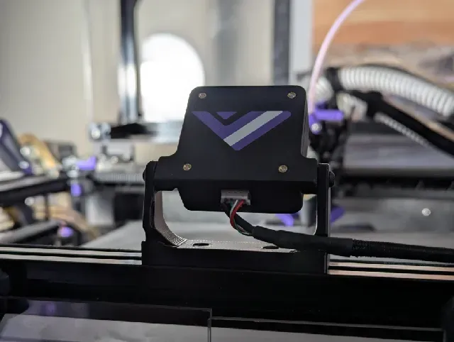
I wanted the camera at the front and center. With how little space there is in this printer, the gopro style mount would have just taken too much space and the toolhead could collide, so I came up with a different way of mounting it.
The case was modeled from scratch, but the core design is pretty similar if not identical for a few elements. I first mocked up the Cam module PCB with most of it's components, just to have a more accurate reference to work with, so that the case can be designed around that.
Since the camera module can be mounted in any of 4 orientations on the back plate, and the pivot joint has a fairly large degree of freedom, you can technically mount this in many orientations. As seen, upside down mount with the cam facing down, the bracket sideways (although this is a bit limited since you can't aim the cam downwards)
All parts are printable without supports, although the default orientation is not the best! Best orientation is as shown here:
Back Plate:
- The base plate has a cutout on all 4 sides for the Sherlock connector, so you can install the module in any orientation you want.
- Added the VZ Logo since, at least in my case, it's front 'n center on the machine, so might as well make it look pretty.
- The hinge mounting points on the sides are serrated (technically every 10 degrees of rotation) on both parts to help give it more grip. This should minimize/eliminate any potential sag over time from heat or etc.
- The hinges are flush to the bottom to allow for more articulation potential, which is more mounting options if you so wish to use this.
Case:
- The height of the case was changed a bit compared to the original. This is to line up with the bottom flat of the IR diodes. It probably doesn't make a lick of a difference, but there's a bit less wiggle room.
- Added an extra groove feature for a bit more pop, because why not
- The case body was modeled to work with 16mm M2 bolts, since that's what fits through the board. As you can see from the pictures, it's just the right length. This is the original length that the case called for, at the time.
- If needed, I can upload a 20mm variant, it's a fairly quick change for me.
- The counterbores have printable geometry, no need to worry about supports or sacrificial bridges.
Extrusion Mount:
- Matching serrations to the back plate, improves grip
- narrow profile
- 18mm deep instead of 20, that way it doesn't rub up against the lid panel
- Two small retention grooves to feed/hold the USB cable through.
Hardware needed:
M2 x 3 x 3 thread insert: 4pcs M3 x 4 x 5 thread insert: 2pcs M2 x 16 bolt: 4 pcs M3 x 8 bolt: 4 pcs M3 T-Nut or Roll-in Nut: 2 pcs
Parts were printed in ASA for mine. Other materials untested, although it should work fine regardless as long as you're decently calibrated.
***NOTES***
- If needed, I can make a variation that threads into plastic for both bolt types in the Back Plate. I went this route for the hinges at least just so I can apply a bit more holding torque. I did the case since I found tiny M2 threads to be finnicky to get right, dimensionally.
- The hole diameter for the M2 thread inserts was slightly increased. My original print (as seen in pictures) was a little too tight. This change has not been tested . The hole used to be 2.8, it was increased to 3mm. With filament shrinkage and tiny holes, this should work just fine, but do let me know if it's too loose.
- The size of the retention grooves in the extrusion mount was updated to be slightly larger from the printed one shown in pictures. I found the original dims to be a bit too tight for the USB cable with the heatshrink there. It would have been fine with just the sleeved portion, otherwise. At the very least, if it's too loose, it's a guide channel for the cable.
- I've uploaded the files in 3 variants:
- Individual parts, just import all the back plate parts together to form one body, and the same for the case and it's parts. I found it mildly difficult to try color painting when you can't just right click the individual bodies and set a color. You can just import the main body without the inlays if you prefer to have a single color look with overhangs. You can print as single color with multi-body as well, but the perimeters will still follow the outline of the logo/inlays.
- Multicolor variant, all relevant bodies combined in one STL.
- Glorious STEP files.



Названия используются только для указания источника результата. Polyzon не аффилирован с перечисленными площадками.