
Бесплатно 
Print in place spring loaded 18650 Battery cell holder / charger TP4056
Printables



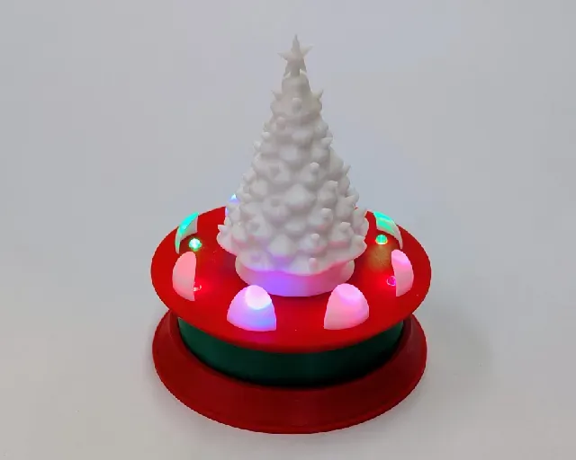

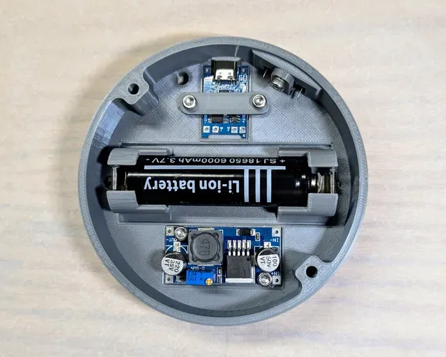

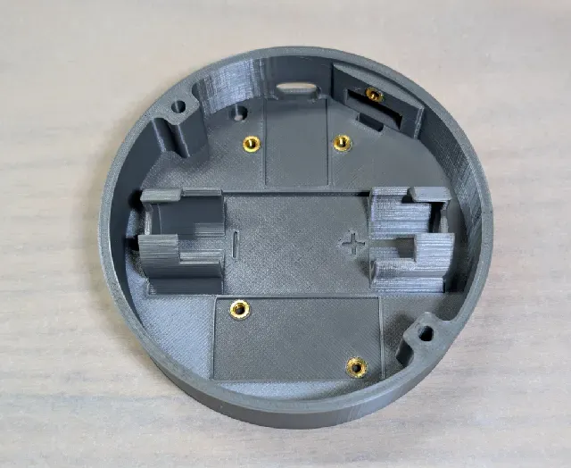
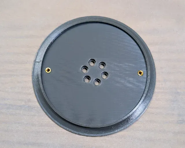




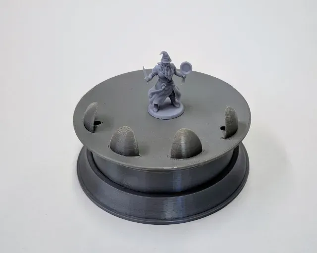



A rechargeable 18650 battery pack forms the core of this set of lighted display stands. The battery pack could definitely be used for other projects too.
- The first configuration uses various arrangements of lights that are embedded in the display platform itself. - The second option uses a pair of pillars that shine lights from the sides . - The third configuration has a pillar that shines light from above . Before anything else I want to give credit for the pumpkin and Christmas tree models in the photos. Credit goes to @Bugman140 for Gourdo the Pumpkin and credit goes to @Reversio3D_1590879 for the excellent Christmas Tree .
I used standard round top 5mm LEDs for all of the designs included here. Other possibilities like micro LEDs or flexible LED filaments would be fun too. Top and bottom decorative rings and platforms allow you to customize the look of your stand.
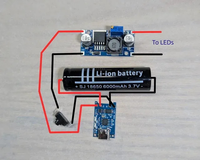
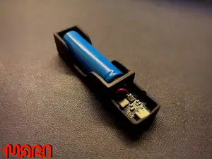
The battery box holds a TP4056 charger to power a 3.7 Volt 18650 battery. The battery is connected to a LM2596 buck converter so you can set the exact voltage you want to supply to your LEDs (usually around 3 Volts but maybe less for some LEDs). There is also a push-button latching micro switch to turn the lights on and off. I used leaf springs as contacts in the battery holder.
To assemble the plastic parts you need:
- 7 M3xL4xOD5 brass heat set inserts, - 5 M3x6 screws (for mounting components in the base) and - 2 M3x30 screws (for connecting the top, base and bottom ring together. Two of the seven heat set inserts go in the underside of the top platform. The remaining five are used inside the battey box for mounting components. See the photos for insert locations if it is not already obvious.
If you do not want to use heat set inserts and screws you may find that hot glue or CA glue will hold components in place well enough.
Here are some links to parts that worked for me. These are just examples. They are not affiliate links.
- TP4056 Chargers - 18650 Batteries - LM2596 Adjustable Buck Converters - Push-button Micro Switches - 8mm Leaf Spring Battery Contacts - 30 Gauge Silicone Wire - M3xL4xOD5 Brass Inserts - M3x6 Screws - M3x30 Screws I am hoping the pictures and parts themselves will be sufficient to help you with assembly. There are a few notes about the electronics below. Feel free to let me know in the comments if I left something out or if my notes are unclear.
SETTING VOLTAGE ON THE LM2596:
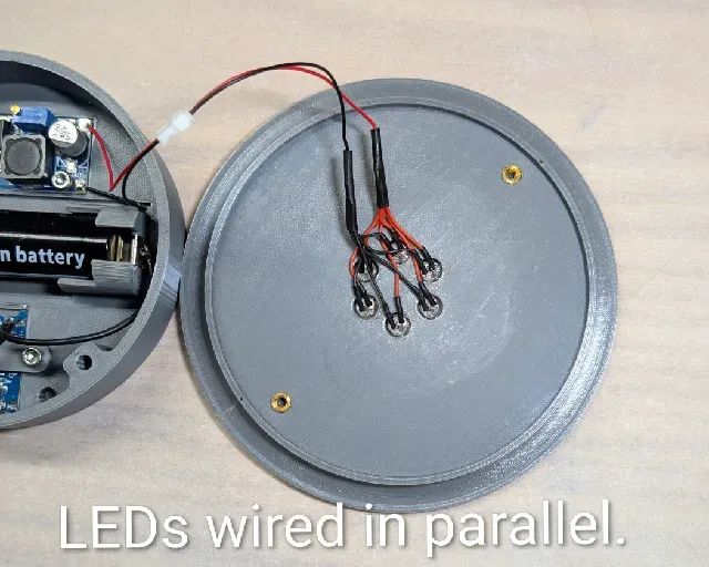
- Connect the LM2596 IN+ and IN- terminals to a 5 volt power supply. (This can be done by connecting it to the OUT+ and OUT- terminals on the TP4056 if you want.) - Use a multimeter to monitor the voltage at the OUT+ and OUT- terminals on the LM2596. Turn the little brass screw on top of the blue box (potentiometer) with a small screwdriver until the output voltage reaches your desired level. Turn the screw counter-clockwise to decrease and clockwise to increase the voltage. Note that it may take many rotations of the screw. WIRING THE LEDs: The LEDs must be wired in parallel NOT in series. That basically means that every LED must be directly connected to the wires coming from the LM2596 module. There is a photo showing one of the LED arrangements wired in parallel.
USING MULTIPLE COLORS OF LED: Different colored LEDs in one circuit will cause the LED with the lowest forward voltage to draw most or all of the current, leaving the other LEDs dim or unlit. You can use resistors to overcome that issue. Google “how to use resistors with LEDs” for details. If you want an excellent detailed lesson on the subject try this video: “How to Calculate the Correct Resistor for LEDs” on YouTube.
CHARGING ISSUES: If you use a smart USB-C charger to plug in to the wall and no charging happens it may be looking for information from the TP4056 about how much voltage to supply. The TP4056 requires 5 volts but most of them cannot relay that information to a smart charger so the charger quits. If you are using a TP4056 that has a USB-C connector you will likely need to either use a dumb wall charger that will only supply 5 volts or use a charger that has a USB-A output because they only supply 5 volts.
CHARGING WITH THE LIGHTS ON: It is possible to have the lights on while you are charging the battery. Doing so may lengthen the time it takes to get a complete charge.
LEAVING THE STAND PLUGGED IN: You can leave the stand plugged in all the time and use it but, depending on who you talk to, doing so may adversely affect the life of your battery. The TP4056 board used in this project is supposed to have battery protection built in but I am uncertain of its quality or limits. I am no authority on batteries so use your own best information and judgement. I hesitate to leave lithium ion batteries plugged in to a charger any longer than necessary.
WHY LM2596? Wondering why I use a LM2596 instead of current limiting diodes or resistors to control voltage? The simple answer is that the LM2596 is usually more efficient, loses less energy as heat and in my experience the battery will keep the lights on longer without dimming. I like that I can dial the LM2596 in to produce the exact voltage and ultimately the effect I want with the lights. If you have other thoughts (or polite outright corrections to my thinking) it would be interesting to hear them.








Названия используются только для указания источника результата. Polyzon не аффилирован с перечисленными площадками.