
Бесплатно 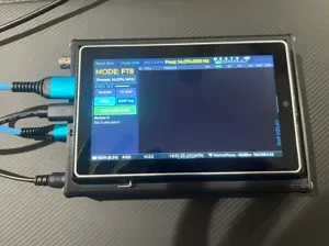
QRP-Labs QMX+ Enclosure Options incl. Panadapter
MakerWorld

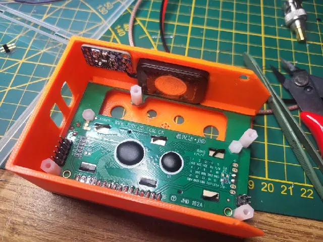
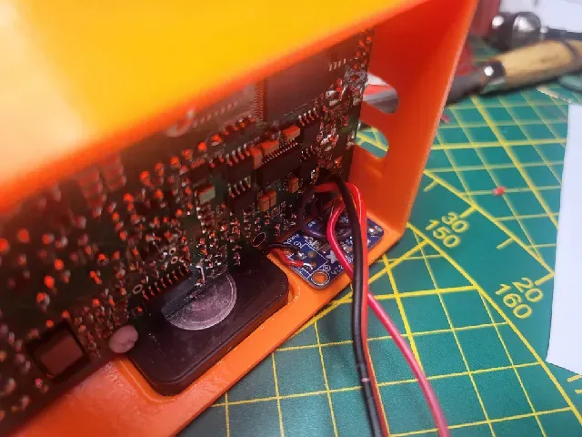


I finally decided to publish this model, since its way too cool for not being out there.
Be warned up front: Its a complicated print. For the Part "BAOFENG_Akkuhalter", you need to print with supports, and select a full support interface with a non sticking material.
I printed the housing in PETG and used PLA as support interface layer. PETG and PLA dont stick very well together, and you can create smooth surfaces on full overhangs.
What you need:
- Both housing parts printed to perfection
- A working QRP Labs QMX, built for 9V Power Supply Voltage !!!
- https://qrp-labs.com/qmx.html
- (I left out power supply socket while assembly)
The following links are affiliate links (I will get a small percentage of the sales without additional costs for you.) This helps supporting my work. The housing was designed specifically around those parts. For Amazon: "Als Amazon-Partner verdiene ich an qualifizierten Verkäufen"
- https://amzn.to/4q2LQOB small buck converter
- https://amzn.to/4qapo6g battery contacts
- https://amzn.to/3YSX780 speaker 4 Ohms / 2 Watts
- https://amzn.to/3L6BL3T class D 2,5W audio amp
- https://amzn.to/4q2CxxS Baofeng battery, in case you dont have one
- https://amzn.to/4pmL7qm M3x5mm screws
- https://amzn.to/4plUiar M3 nuts
Assembly Instructions:
- mount speaker in corresponding recess in "QMX_Housing_OT_BESCHRIFTET"
- speaker comes with 3M tape
- cover metal on backside of speaker with electrician tape or similar, to prevent accidental contact
- push audio amp in the recess on the 2 tiny knobs with corresponding holes
- cut and solder speaker cables to audio amp output
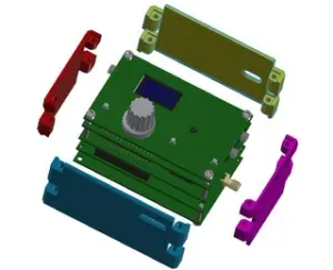
- Slide in QMX Display PCB (See pic)
- Push on main PCB with Display/Button PCBs
- Secure PCB Stack with Nylon screws
- solder "Audio Amp GND" to "GND on Main PCB"
- solder "A+ of audio amp" to following "pin of X202 on Main PCB"
- IF you solder it to the correct Pin, Audio-PA is being disconnected, once headphones are plugged in
- Solder red and black wire to + and minus on main PCB
- Take one of the spring pin assemblies
- carefully cut off one pin from the assembly
- from the remaining 5 pins: carefully pull the middle pin without breaking the plastic
- push those 4 pins with the springy side forward in the "BAOFENG_Akkuhalter"
- Prepare buck converter by cutting the trace "adj"
- Close Bridge for 5V
- Solder red an black wire to IN+ and GND
- Solder 2 red wires (from main pcb and buck converter pcb) to left 2 spring contacts. Try to bridge both left contacts for redundancy if one contact fails.
- Solder 2 black wires (from main pcb and buck converter pcb) to right 2 spring contacts. Try to bridge both right contacts for redundancy if one contact fails.
- See labels + and - on print
- Solder another set of wired to GND and VO+ of buck converter PCB




Названия используются только для указания источника результата. Polyzon не аффилирован с перечисленными площадками.