
Бесплатно 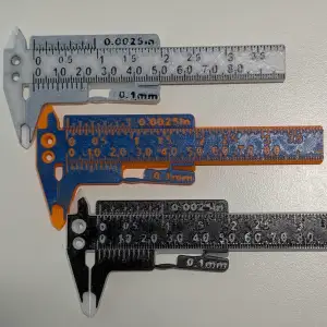
Clamp Caliper (printable pocket caliper w/ clamp)
Creality Cloud



Clamp Caliper (printable pocket caliper w/ clamp)
Features:
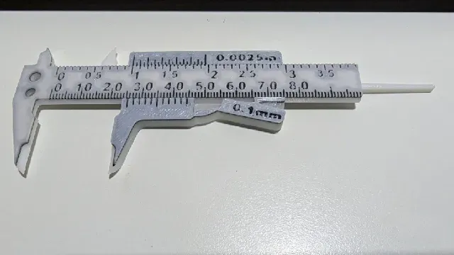
- Measures up to 80mm by 0.1mm (0.004 in.) increments or up to 3 inches by 0.0025 in. increments--depending, of course, on the accuracy and precision of your printer and printed material shrinkage. (See below for how to adjust the accuracy if the first print is not to scale.)
- Measures outside lengths with external jaws (bottom-left)
- Measure inside lengths with the internal jaws (top-left)
- Measure depth along an edge with the left ends of the ruler and slide
- Measure the depth of a hole with the slide's depth probe and the right end of the ruler
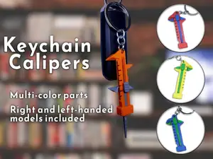
- Small enough to fit in a pocket, so it is borderline useful on a key chain.
- Has two key-chain-sized holes (3mm) for those who don't mind something this large on their key chain. (The upper hole goes through both the ruler and slide, so both will be attached to the key chain, and it would need to be removed for use. The lower hole only goes through the ruler, so the caliper can be used for most applications without removing it from the key chain when attached through that hole. There is a minor risk of losing the slide if this hole is used, but if clamped in place, that should be minimized. And you can always just print another slide if you lose it.)
- Has measurement marks to the very end of the ruler, allowing for a full 0.1mm/0.005in precision all the way to 80mm/3in.
- Has an integrated clamp to hold a measured position for reading.
- Has a printable cover, in case you don't like the pointy tips stabbing your leg while in your pocket or you just want to protect the tips of the jaws and depth probe. The cover has a small retention post that inserts into the back of the slide to keep it semi-attached and moved out of the way for taking measurements, but it can also be completely removed and reattached later.
Clamping:
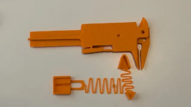
A compliant mechanism clamps the slide in place while moving from an item measured to a viewing position, helping to ensure you read what you measured. Squeeze the slide to clamp it in place against the ruler. Press the lower-right corner of the slide to unclamp it. (See the video for a demo.) The first time you operate the clamp will be the hardest. It might even help to use pliers to engage it the first time. After it has been engaged once, engaging and disengaging should be much easier.
Readability:
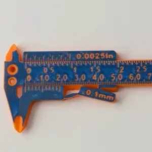
You can print the Clamp Caliper on a one-color printer. Legibility can be improved by pausing the print and switching to a contrasting color at the base of the markings (just below the top layer), and then switching back for the top layer--like the white caliper with black markings in the photos. Or just print the top layer in a contrasting color--like the blue-on-orange, or black-on-white calipers in the photos. If you have a CMS or other material switching system, printing a contrasting layer should be simple.
Accuracy:
To adjust for shrinkage of the printed material as it cools, print out the slide, then measure it with a trusted ruler or caliper. Alternatively, in your slicer, you can adjust the scale in the x-direction to compensate for any discrepancy and reprint. For example, if your test print measures 79.2mm between the 0mm and the 80mm marks, you will want to reprint it slightly longer on the real print. To do this, set your x-scale in the slicer to 80/79.2, which is 1.01 or 101%.
Functionality:
If the slide is too tight or too loose, it can be scaled up in the y direction (default orientation) to adjust. Alternatively, the ruler could be scaled down in the y direction.
Pressure Ball:
The clamp on the slide includes a separate "pressure ball" object to allow for adjusting the grip of the clamp mechanism. If the clamp mechanism is too tight or too loose, the position of the pressure ball can be adjusted. Viewing "objects" in your slicer should allow you to see and select the pressure ball more easily. Moving it 0.1mm in the y direction will increase the clamping force, while moving it in the negative y direction will decrease the force. Some slicers see the small pressure ball and think it is at the wrong scale when importing the slide. If it asks if you want to adjust it or use different units, answer "no," or you will get a gigantic ball along with the slide.
Settings:
I printed with the following settings:
Nozzle 0.2mm
Layer 0.1mm
Line width 0.25mm
Nozzle o.4mm
Layer 0.2mm
Line Width 0.4mm
Wall Generator: Classic (I generally use the Arachne wall generator, but it does not do a good job on the small tick marks on the ruler and slide.)
To adjust for filament shrinkage, I found it best to account for it in the filament settings.
PLA Shrinkage (XY): 99.8%
PETG Shrinkage (XY): 99.7%
Just check after your first print. Different materials, brands, and even batches may have different shrinkages.
How to read the calipers:
Reading millimeters is straightforward. Referring to the first photo, the one with the white caliper, black markings, and red, green, and yellow arrows and labels. The yellow arrow just shows the clamp in the clamped position. Let's read the measurement in mm. The bottom scale is in mm. The first mark on the slide is just past the 12mm mark, so we know we have more than 12mm but less than 13mm. Let's note that as 12._mm for now. To find the part after the decimal, we check to see which line on the slide aligns best with the closest mark on the ruler. The first line is the 0/10ths mark and doesn't align. The second line is 1/10 and is close, but not right on. The next line is the 2/10ths line, and it aligns pretty well. The one after that is the 3/10ths line, but it is misaligned about the same distance as the 1/10th line, but on the other side of the mark. This means the 2/10th line is most aligned, so we add 0.2mm to the original 12mm reading on the ruler to get the total measurement of 12.2mm.
For inches, marked on the top side of the ruler, it's a little more complicated, because the ruler has marks at ever tenth of an inch, and between those, smaller ticks at each 1/20th of an inch. So we can measure to the nearest 0.05 of an inch directly on the ruler. The slide also has more markings on the inch side than on the mm side. The largest marks design 5 divisions of 0.01 inches each. And each of those is divided into four divisions of 0.0025, with the middle mark designating 0.005 being slightly longer than the marks for 0.0025 and 0.0075 inches.
So to get the same 12.2mm measurement in inches, we note that the first mark on the top of the slide is just short of the 0.5 inches mark, but past the 0.45 inches mark. So we have at least 0.45 inches, plus a little more. Let's use the scale on the slide to figure out precisely how much that 'little more' is. Looking for which mark on the slide aligns best with the closest mark on the ruler, we have to look pretty far to the right. We go past the 0.01 mark, the 0.02 mark, and even the 0.03 mark. Looking at the 0.0325 mark, it's close, but the 0.035 mark is closer. The 0.0375 mark is now further away, and on the other side, so that means the best aligned mark is the 0.035 inch mark. If we add that 0.035 inches to the original 0.45 inches we measured directly on the ruler, we get 0.45 + 0.035 = 0.485 (inches).
That's theoretically the same measurement, just in inches rather than the 12.2mm we got from the other scale. Let's see how consistent the two sides are after the imprecisions of FDM printing and material shrinkage come into play. By definition, 1 inch equals exactly 25.4mm.

Названия используются только для указания источника результата. Polyzon не аффилирован с перечисленными площадками.