
Бесплатно 
Better RC Sailboat Rig Tension Meter
Printables








Better Model Yacht Launcher
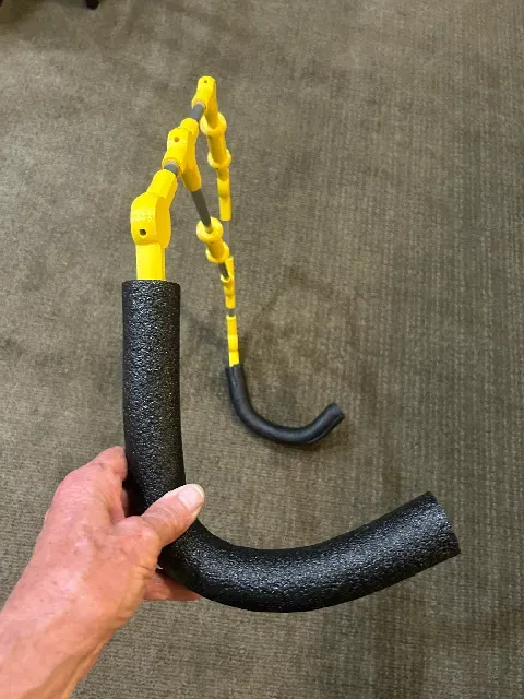
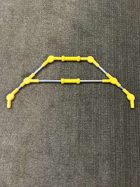
Design allows the launcher to lie flat for one plane for travel. Then for usage you will rotate the lower curved bottom curves tubes into position to cradle the model yacht for launching and retrieval.
Rotatable curved arms support the model yacht at the bow and stern and allow the model sailboat/yacht to launched and retrieved with bending over. Launcher is ideal for launch and retrieval from a shoreline or a dock.
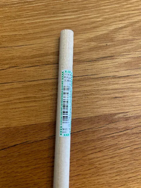
Launcher design is easily customized for use with any model yacht/sailboat class by resizing the tube lengths and curves. Launcher is currently sized for a Canterbury J model yacht. Sturdy enough for a J boat or an EC12 model sailboat. 1/2" OD wooden dowels were used to determine the best actual lengths for aluminum tubes.
Design can be used by left or right-handed sailors because both lower curved arms will rotate clockwise or counterclockwise. Aluminum tubes are 0.5" OD and readily available in most big box hardware stores or on-line. 3mm SS cap head fasteners and 3mm heat set threaded inserts are also used. Jessie PETG filament and two pieces of foam covering complete the parts list.
Printed Parts
Upper/Lower Connector, print 4
Middle Connector, print 2
Handle, print 2
Curved Tube End Plug, print 2
Straight Tube End Plug, print 10
Bending the Curved Tubes
I bent the curved tubes by partially filling them with sand and using a ~12" length of 3/8" OD rod partially inserted into the length of tube at each end. One rod end was secured in a vice and the other rod's free end was protruding beyond the end of the tube. I then used the unrestrained rod end as a lever arm to make the tube bending easier. Sand inside the tube between the two rods prevents the tube from collapsing or crimping whilst being bent.
Install Heat Set Inserts
Install two 3mm x 5mm x 5.7mm heat set inserts into each Handle
Install one 3mm x 5mm x 5.7mm heat set insert into each Straight Tube End Plug
Install one 3mm x 5 x 4mm heat set insert into each Middle Connector
Tube End Plugs Installation
CA glue a Curved Tube End Plug into the lower end of each curved tube segment and a Straight Tube End Plug into the upper end of each curved tube segment. Avoid allowing glue into the threads.
CA glue a Straight Tube End Plug into each end of the four straight tube segments. Avoid allowing glue into the threads.
Assembly tips
Thread a bolt through the left Middle Connector and into the left end of the lower horizontal tube Straight Tube End Plug. Insert a Handle onto this tube. Thread a bolt through the right Middle Connector and into the right end of the lower horizontal tube Straight Tube End Plug.
Insert a diagonal tube length into the left and right Middle Connector.
Insert an Upper/Lower Connector onto each end of the left and right diagonal tubes.
The are two bolts that need to be threaded thru each Upper/Lower Connector and into the corresponding threaded Straight Tube End Plug. Each of the two bolts installed into an Upper/Lower Connector fit into different depth internal recesses.
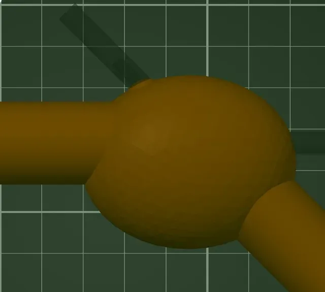
Note that the Upper/Lower Connecter has small protrusion around one of its bolt holes. Install this bolt first. The first bolt installed into each of the four Upper/Lower Connectors is threaded into the Straight Tube End Plug in the upper and lower ends of the left and right diagonal tubes.
Pay attention to order of bolt installation into each Upper/Lower Connector. Be sure this first installed bolt in each Upper/Lower Connector is fully recessed before installing the second bolt into each Upper/Lower Connector. If the first bolt installed into an Upper/Lower connector is not fully seated into its recess, then second bolt cannot be installed.
The second bolt installed into each Upper connector is threaded into the upper horizontal tube which holds the upper Handle.
The second bolt installed into each Lower Connector is threaded into the upper end of a curved tube segment.
The bolt that is threaded into each Lower Connector into the upper end of each curved tube segment should only be sufficiently tightened such that the curved tube segment is free to rotate 90 degrees CW or CCW. This partially tightened bolt allows the launcher to be transported with all of the tubes in a single plane while also allowing the rotation of the curved tube segment so that the curved tubes can be placed underneath the model yacht for launching and retrival.
Parts list
PETG - I used Jessie brand, Yellow
4 - Upper/Lower Connectors
2 - Middle Connectors
2 - Handles
10 - Straight Tube End Plugs
2 - Curved Tube End Plugs
12 - 3mm heat set threaded inserts 3mm x 5mm x 5.7mm Ruthex brand. Installed in Handles, Upper/Lower Connectors, Tube End Plugs
2 - 3mm heat set threaded inserts 3mm x 5mm x 4mm Ruthex brand. Used in Middle Connectors to secure connection to a diagonal left and right tubes.
14 - 3mm x 20mm SS cap head bolts. Used to attach tubes segments to Upper/Lower Connector and Middle Connector. Threaded into Tube End Plug thru each connector and into tube segments.





Названия используются только для указания источника результата. Polyzon не аффилирован с перечисленными площадками.