
Бесплатно 
Elegoo Centauri Carbon Canvas Relocation & Riser, LED Light Strip Ready
Printables


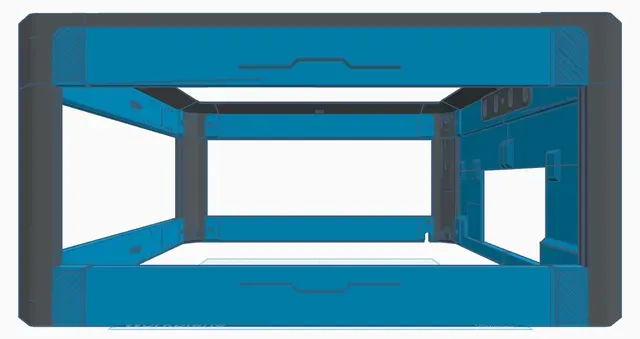
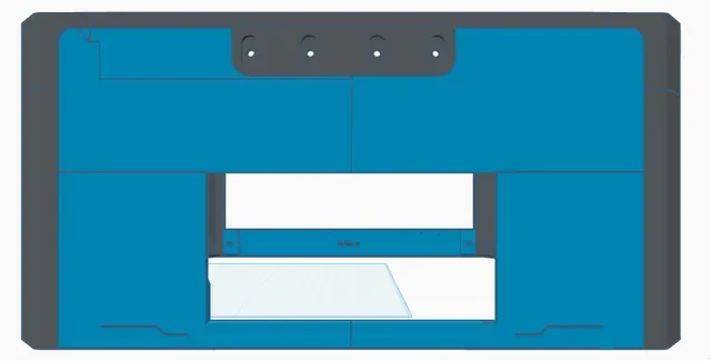






EDIT - UPDATE 15 August 2026 Based on some feedback, I've replaced the 3MF file with one that contains better plate labels and support blockers / enforcers. The original 3MF file has been removed to avoid confusion. There is a solid front-back upper panel OR a vented panel with louver - its your choice which option you'd like to make. 21 August 2026 Based on some additional feedback, I've added a revised right-side panel set with some improved alignment pins - no more tiny pins and holes. Substitute these for appropriate parts from the "main" 3MF file. Per request, I've also added "solid" (no window) panels for the left side and rear panels. These are split into 2 pieces in order to fit on the ECC build plate. Substitute these panels for the appropriate detail blocks and upper / lower panels. The 3MF files for these new panels have support enforcers and blockers added. The new parts should fit with the frame components (uprights, top corners and top rails) but, please note that I have NOT printed these panels myself however, I am confident in their dimensions.
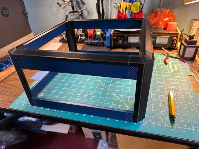
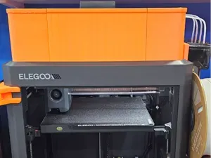
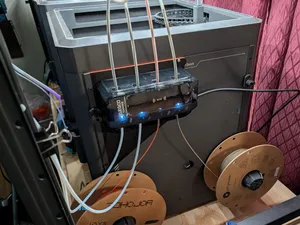
Preface My riser augments and follows the physcial design characteristics of the Elegoo Centauri Carbon printer. The corners and top contour lines match that of the printer itself so the original glass lid can still sit on top. I designed a part with openings in it to allow the PTFE tubes to pass into the machine and avoid the big slanted hood cover design I've seen on many other Canvas risers. There is also an opening for Canvas cable and optionally any LED lighting you may wish to add. This riser design keeps the orignal Canvas and spool mounting locations.
The physical dimentsions of the Elego Centauri Carbon printer without the Canvas are 400mm wide X 407mm deep x 494mm high. The Canvas unit is 168mm wide, x 61mm deep x 88mm high. The Canvas mounting plate is 168mm wide x 8.5mm deep x 98.5mm high.
Because the printer is a little deeper than it is wide, the front and back components of this riser are not interchangeble with the left and right side components. The finished riser dimensions are 400mm wide x 407mm deep x 200mm high. The printer dimensions with the riser installed are 400mm x 407mm x 694mm. If you have the PA vented riser on top, that adds another 50mm for a total of 744mm high. All of the components in my riser have an embossed part number or location on the inner-face of the part to assist with assembly.
The distance between the corner uprights is just a little too long to fit on the print bed. The small "detail blocks" are used to get that measurement down to a prrintable size so that the upper and lower side panels will fit on the bed. And these blocks add a nice design accent that mimics the stylistic elements found on the printer.
It may seem obvious but, I've "over-engineered" this riser a bit. Not from a strength standpoint but from a general complexity perspective. There are a LOT of parts (42) but they do go together well, just not quite intuitively.
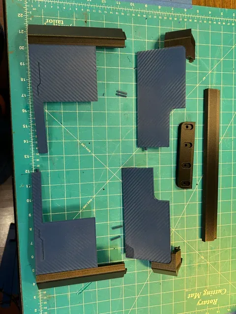
I printed all parts in PETG-CF. I'd recommend PETG as a minimum for the higher temperatures that may occur when heating the print chamber. There are four panels that interlock for the side that surrounds the Canvas.
Note: I do NOT have any affilation with or get anything from any links provided.
You will also need the following items;
Qty
Item
Description
Source
2
Polycarbonate Sheets
12" x 24" x 3mm thick Polycarbonate sheets for window panels
https://www.amazon.com/gp/product/B01KZG8L0Y/ref=ox_sc_saved_image_1?smid=A1FWWCVO9POVQF&psc=1
Double-sided tape
optional - for mounting riser to printer
CA glue
optional - for final assembly
Preparation I recommend the polycarbonate panels listed for the window panels as they will tolerate the temperatures in the printer when enclodsed and heated for the higher chamber temperature filaments such as ABS or ASA that the ECC1 supports. However, if you can locate an equivalent product from another source, go for it. The polycarbonate panels will need to be cut to these dimensions: (thin polycarbonate sheets 3mm thick or less can be scored with a sharp utility knife and snapped at the score-line)
Qty
Position
Size
1
Left
343.5mm (w) x 113.5mm (h)
2
Front / Back
338.5mm (w) x 113.5mm (h)
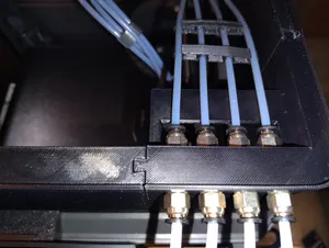
Plan your color scheme if you want to use different colors for various components. I used blue for the accents and black for the riser frame (uprights, top corners, and spreaders). Determine if you want the vent panels or solid panels above the windows. There is a different "detail" block for the lower back corner to accommodate the cable for the Canvas. You can also pass wiring for additional LED lighting into that opening. The PTFE tubes will need to pass through ports in a block on the Canvas side panel. See below for details.
Printing My print settings were; 0.40 nozzle, 0.20 layer height, 3 walls, 10% gyroid infill. Supports are recommended for the top corners, uprights and Canvas side panel components tongues and pegs. Support blockers are placed in the 3MF file for the grooves in the top corner parts. Most holes and all of the top rails and vent panel don't need any support (but they aren't "blocked"). Estimated time to print (Orca, with the above settings) >>>> Estimated filament used (also, from Orca) >>>>
Print the all of the components in at least PETG, (I used Elegoo PETG-CF) or other higher-temp capable filament such as ABS or ASA. The STL file contains a lot of pieces. When you "split" it to the objects you may want to retain the Z-axis postioning. The 3MF file (which I produced in Orca Slicer 2.4.2) has all the components laid out on build plates and labeled. Componets should be printed as shown. However, I do recommend that the top corners and uprights be printed individually. I only grouped them to cut down on the number of plates. Also, the detail blocks probably should be printed in sets of 4. That way, a failure won't take out the entire set. Most components don't need supports except for the top corners. The Canvas surround is made up of 4 panels with dovetail tongues that fit in the groves of the uprights. There are 4 vertial alignment pins to glue in to the lower panels that will keep them connected to the upper panels. And there are embeded horizontal pins and holes for the front-to-back connections of the right side panels as well as for the top rails to the corners. Update: 21 August 2026 - see the "NEW PINS" 3MF
Assembly Test fit everything before applying any glue. Use CA glue sparingly as most parts fit together snug by design. (I didn't use any glue!) Power off and unplug the printer.
Begin by temporarily removing the Canvas head unit from the printer. You will need to unload / remove the filaments and then remove the PTFE tubes from the top of Canvas in order to feed them through the tube block later. I labeled mine before removal to make reassembly easy. Press down on the fitting on the top of the Canvas for each tube and pull the tube straight out. Next, remove the cable from the Canvas unit. Lastly remove the 3 screws mounting the Canvas to its mounting bracket. Set these parts aside for reassembly later.
The following steps were done on my workbench. Start wth the lower right-side compoents that will go aroud the Canvas. The right side parts around the Canvas are probably the most challenging part of the assembly so we might as well start with it.
Assemble the right-front upright B2 to the lower-front panel Z6 via the dovetail tongue and groove. If these are tight, a few gentle taps can help. If the parts won't go together, make sure the components are "clean" (nothing sticking out or warped). Assembe the right-rear upright C2 to the lower-rear panel labeld Z5 in the same manner. Connect these corner uprights and panel assemblies, aligning the horizontal pin and hole. Now insert two vertial pins in the lower-front panel and two more in the lower-rear panel.
Next, assemble the lower rear panel with Detail blocks Y3 and Z4. The Z4 block has the opening for the Canvas cable so make sure that is at the C2 corner. Slide the Z4 block into groove of the C2 corner upright. Connect Detail blocks Y3 and Y4 to the lower front panel. Slide the Y3 block into the groove of the B2 corner upright.
Now assemble the lower left side panel with Detail blocks Y3 and Y4. Slide corner D2 onto the Y4 block of the lower left panel. Slide corner upright A2 onto the Y3 block of the lower left panel.




Названия используются только для указания источника результата. Polyzon не аффилирован с перечисленными площадками.