
Бесплатно 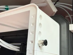
PTFE Skylight for CC1 Canvas Relocation & Riser
Printables
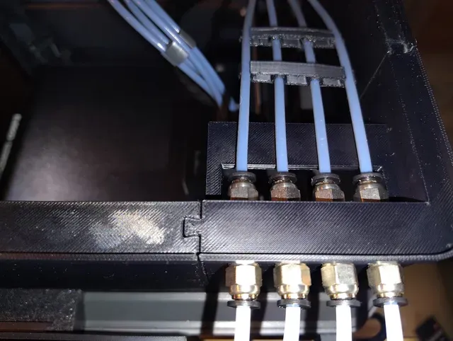


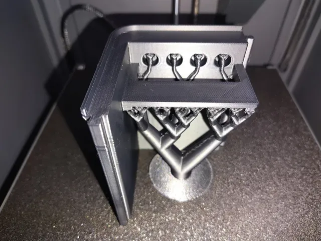


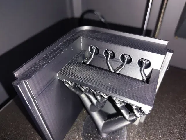
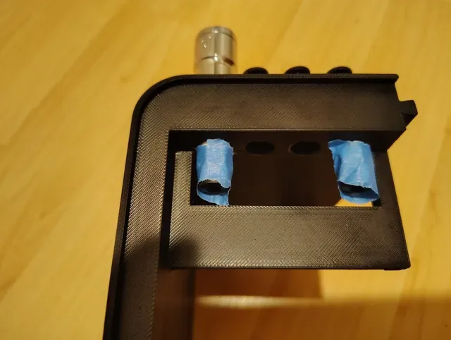


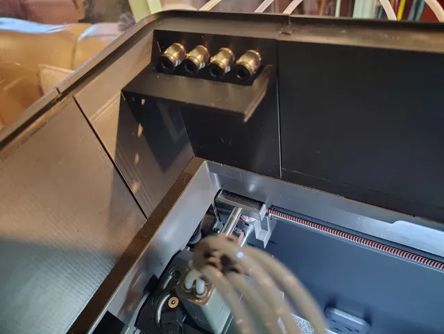
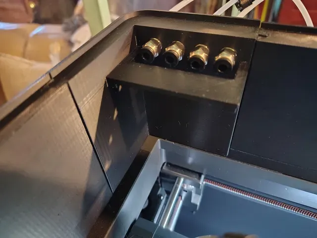
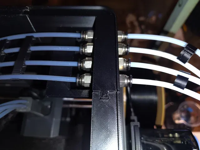
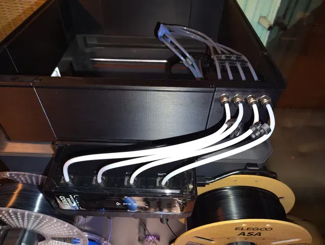
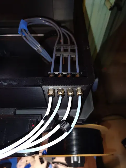


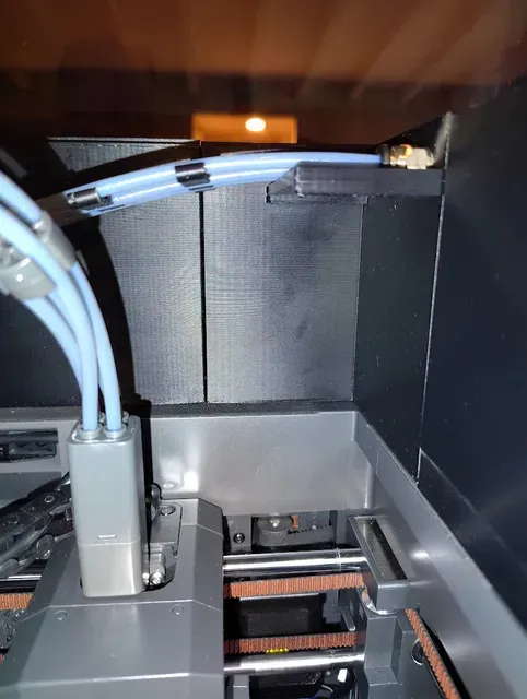


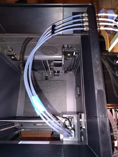


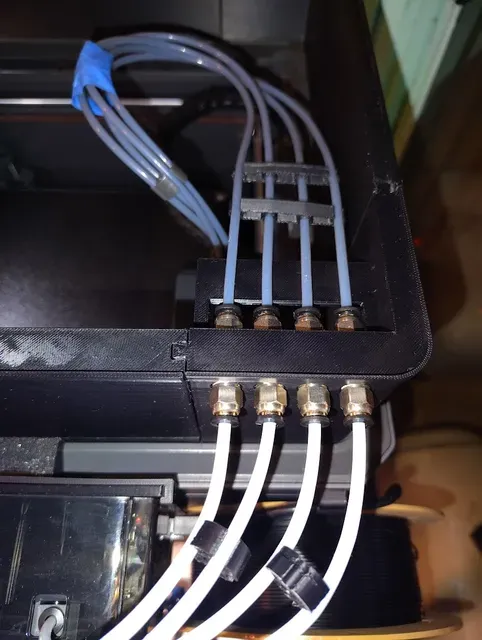
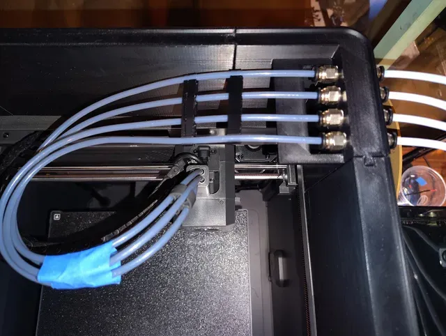


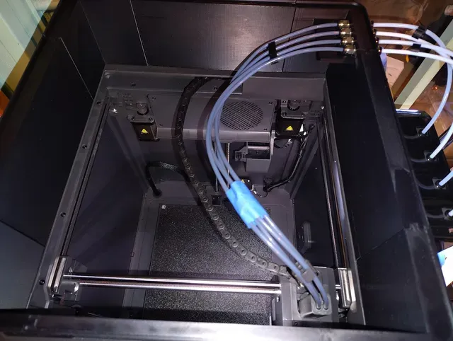


- Description for this remixed part: Rear right corner with added inner PTFE tubes shelf (to keep the inner 4 x PTFE tubes straight and level at the connectors exit point) for the CC1 Canvas Relocation & Riser by @ALExtremeError (aka @AEE ) project (it replaces the "AEE_45_Deg_Corner_RR_PTFE" no LED version part, filename = “ aee_corner_rr_ptfe_45_degree_no_led.stl ”, in that project), the front inner PTFE tubes shelf was added to avoid filament jams, that causes jamming to sometimes occur (sometimes occuring mid print, especially if a filament change was made during a print, and other times could be seen when pushing the filament manually by hand through the inner and outer PTFE connector pairs), in the middle of the rear right corner part, where the tube pairs for each of the 4 x PTFE connector pairs and the tubes that run through them meet up, that must be kept as straight and level as possible, on both sides of the 4 x PTFE connector pairs, for the filament to pass thru them without it jamming up there if the inner 4 x PTFE tubes aren't straight and level as to match the outside 4 x PTFE tubes, or if the inner PTFE tubes are at too much of a downwards angle compared to the outside tubes, mainly due to the lack of a place for the first portion of the inner 4 x PTFE tubes to rest/sit on, in the first 2" or so of the inner PTFE connectors) for the “ Elegoo Centauri Carbon Canvas Relocation & Riser ” project (it replaces the original "AEE_45_Deg_Corner_RR_PTFE no LED" part in that project). The problem, that I have seen first hand with the origin riser project installed on my CC1 with Canvas, is in the most crucial first 2" of the 4 x PTFE tube runs, where the tubes exit out the inner PTFE connectors port (which must be quite straight and level for filament to feed through that channel/path on both sides of all 4 of the PTFE connector pairs in that case), and this remixed part which now contains a shelf exists to address that problem. This remix part is only compatible, to replace the original part with, with the single " Pass-thru Holes: 4 holes in the rear right corner for PTFE tubes. Requires 8 x PC4-M10 Pneumatic Quick Connector Fittings ." variant of that part, not any of the other variants of that RR corner part that either A. is the "with LED strip" variant, or B. does not utilize PTFE connectors and only has pass-thru holes; this remix part is made to replace the RR corner "without LED strip" part. The added shelf is thick & substantial and it won't bend under load, and the shelf doesn't interfere at all even if the tool head moves to that corner in full. The origin project's web link is: https://www.printables.com/model/1782738-elegoo-centauri-carbon-canvas-relocation-riser-led . The complete photo album of this remixed part, showing it printed, and showing it installed on the linked relocate & riser project, is here: https://photos.app.goo.gl/Etoiijv6s5rri6K79 .
- Files included: I've included the .3mf, .stl, .step, .skp (SketchUp format, where the "Export" function in Fusion v2704.1.53 app was used to generate that file), and the native .f3d (Fusion v2704.1.53 app, for which the Fusion app was utilized to edit the original part to create this remix part) files.
- Printing Specs (Reference Profile):
- Material: PETG, ASA, or ABS (you may be able to just get away with using PLA+ filament for this remixed part and for the origin riser project, but the inner temperature of the printer when printing with high temp supported filament may warp PLA filament due to the much lower melting point of PLA filament in general.
- Nozzle Temp: 280°C (PETG should utilize 250°C, like the original origin project has specified in the desc. section in it).
- Bed Temp: 110°C (PETG should utilize 70°C, like the original origin project has specified in the desc. section in it).
- Layer Height: 0.20mm (I only tested with 0.20mm, and Elegoo ASA filament). It takes much longer to print this part at 0.16mm and I don't think it'd be worth it.
- Walls and Top/bottom shells (settings in OrcaSlicer 2.4.2): "Wall loops": 2, "Top shell layers"; 6, "Top shell thickness": 1mm, "Bottom shell layers": 6, "Bottom shell thickness": 1mm; those 6, 1, 6, 1 "Top/bottom shells" settings, that differ from the default values in OrcaSlicer, will make the entire part stronger (no matter how many wall loops that you utilize). It will be a bit stronger than that with 3 wall loops but the latter does add quite a bit more filament, and anything over 3 walls would be overkill for this part, as it isn't so weight bearing or stressed. I enable "Arachne" for the "Wall Generator" setting as well in OrcaSlicer 2.4.2, in the "Quality" section (not available in older versions). If using 3 walls make sure to enable the special "Walls printing order": "Inner/Outer/Inner" setting in OrcaSlicer for added strength (which has no effect if using less than 3 walls).
- Sparse Infill: "Sparse infill density": 11%, "Sparse infill pattern": Gyroid, "Z-buckling bias optimization (experimental)": Enabled. The latter option is optional, but I think it makes for a bit stronger supports.
- Support: For this part (and for the origin project as a whole before that) I tested and confirmed with only one support type, which was the "Organic Tree" support type; I did not try any other support types. In that case you will also be required to change the default "Support" section > "First layer expansion = 2mm" setting in the slicer app to a much larger value, in my case I used "Support" section > "First layer expansion = 18mm", to make it so that the base/bottom of the large front tree support doesn't break free mid print (as it will be under a lot of stress/weight once the printer starts printing the shelf portion of the part). I used the default OrcaSlicer 0.2mm top and bottom Z distance. Please make sure to read the further detailed support and brim related notes in the additional " Print Settings (More in depth description)" paragraph below, for addition notes regarding "Supports" and "Brim" related slicer settings to pay special attention to for this remix part to be able to print with 100% success on your CC1 printer.
- Brim: I'd highly recommend enabling an outer brim (or at least mouse ear brim), that is larger than the default value, due to the size of this part, especially if your bed adhesion isn't perfect with your printer & filament type utilized. I'm forced to enable an outer brim on nearly every part that I print on my CC1 printer if I utilize Elegoo ASA filament, otherwise the part that I'm printing will likely break free from the print bed (but I don't need to do that if I utilize other filament types, such as Elegoo PETG or Elegoo PLA+).
- Installation of this remixed part : For existing users that have already printed the full riser and that full riser is installed, and they now need to retrofit the original rear right corner part with this remixed rear right corner with shelf part, you will only need to print this single remixed rear right corner with shelf part, then be careful to remove all of the supports from the base and the holes (which should be easy to remove, if the Supports related settings in the "Printing Specs" are utilized), then remove the 8 x PTFE connectors from the original part (or install new ones if you have them to save time, or if you only want to test this remixed part out but you want to keep the original part with the connectors in-tact / as is for now), then install the 8 x PTFE connectors that this project calls for into the remixed part, which you will have to know will differ a bit since either a closed or a larger 10mm wrench likely won't be able to affix to at least the 2 out of 4 outer most PTFE connectors on each side of the remixed part, due to the arms of the shelf do protrude into that area, so you will need to utilize either a smaller closed 10mm wrench, that is a compact version, or you will need to switch to using an open wrench instead (optimal), and take note not to overrighten the 8 x PTFE connectors, just screw them in enough to cover the threaded portion on each, and make sure that all 8 of them are flush with each other, or match up in how much you had to turn them by visually inspecting and comparing each one as a group, then I'd suggest manually by hand passing through a single short cut piece of filament into each of the 4 x PTFE connector pairs to make sure that it doesn't snag or jam in the middle of each of the 4 x PTFE connectors pair before continuing to get the remixed part placed onto the printer (to save time in case you have to take it back off due to needing to tighten it more, which will be awkward to do on the inner 4 x PTFE connectors at least), then disconnect only the end of the tube from both ends of all 8 x PTFE connectors on the inner and outer sides of the existing rear right corner part, and leave them all hanging there, then slide the original part up and off of the installed riser side pieces that surround it, then slide this new remixed part down and on to the installed riser side pieces next that will surround it, until it is flush with the other riser side pieces, then reconnect the tubes into the 8 x PTFE connectors, on the inner and outer sides of the rear right corner part, and make sure that all of the connections are secure, and re-install any PTFE tube clips or reposition them if needed, due to the added shelf that may interefere there. Or for new users you would print the entire origin project, minus the original "rear right corner no LED" part, and print this remix instead for that last item, and during the install of the remix part, the above instructions still apply, minus the bits about removing the existing 8 x PTFE connectors, and minus having to remove the original rear right corner part from the already installed full riser.
Extended Print Settings instructions (more advanced and in depth instructions to pair with what is stated in the "Printing Specs" section above this, which is required for this remix part to be able to print with 100% success, without failure): PETG, ABS, or ASA for temp resistance. 0.2mm layer height. 2 wall loops. 10 - 15% Gyroid sparse infill (there is no need to go higher than 15% from what I tested). The added PTFE tubes shelf portion of this remix part not only requires supports to be enabled, but due to the size of the shelf and where the PTFE holes exist (on the inner side), where the supports tree has to run to both the shelf and the PTFE holes (on the inner side), where both of those items are inner elements of the model, it will require changing the default "Support" section > "First layer expansion = 2mm" setting in the slicer app to a much larger value, in my case I used "Support" section > "First layer expansion = 18mm" (which also matched my "Outer Brim = 18mm" setting that I also changed from the default 5mm value. Supports are 100% required for this remix part to be able to print with success, mostly due to the added PTFE shelf portion in this remixed part (do not attempt to print without Supports enabled). I would also recommend to in "Others" > "Brim" enable Brim with the "Outer Brim" type and using a "Brim width" of 18mm, which is highly suggested to avoid warping, and to avoid the large front tree support from falling off the print bed, which it likely will with the default "First layer expansion = 2mm" setting in the slicer app, which equates to only 2mm of filament gets added to the base/bottom of the large front tree support, which if that setting is left at the default value, will cause the base of that large front tree support to break free mid print once it starts to print the shelf portion (as it will be under a lot of stress/weight once the printer starts printing the shelf portion), which I would recommend to increase to 18mm in order for the base/bottom of the front tree support to stay in place through the entire part print. The rest of the settings, that either are not stated or pointed out in this " Print Settings " paragraph, as contained in that text, and are not seen in the additional " Slicer Settings" section below , can be kept at your slicer default 0.2mm profile. PLA filament may work but it isn't recommended due to the melting temperature of PLA versus the other stated filaments above.
Features:
Specifically designed to keep the inner 4 x PTFE tubes straight and level with the outer 4 x PTFE tubes, to greatly limit the chance of (mainly downwards direction) bending on the tubes in the most crucial first 2" of the inner 4 x PTFE tube runs path, that must closely match up (in order to be very straight and level with each other) to the outer 4 x PTFE tube runs (where all 4 pairs of those tube runs must be quite straight and level for filament to feed through that channel/path on both sides of all 4 of the PTFE connector pairs in that case, otherwise filament jams can occur), with the addition of a 41mm long inner PTFE tubes shelf, that is level with the exact bottom portion of the 4 x inner PTFE tubes (4mm OD), with a 19mm gap (hole) at the start of it, to allow for the inner 4 x PTFE connectors to screw in without blocking that, to the front of the rear right corner part to help deal with filament feed causes jamming to sometimes occur (sometimes occuring mid print, and sometimes occuring when pushing the filament manually by hand through the inner and outer PTFE connector pairs), that are commonly discussed in the origin project's comments, where the PC4-M10 connector couplers and PTFE tubes meet. The added shelf portion was designed to fit just enough of the PTFE tubes run that is needed to keep it straight and level / flat with the inner 4 x PTFE connectors, where the filament feeds through the currently loaded PTFE connectors pair. The shelf portion was made with strength in mind and every edge on the top of the shelf that a PTFE tube will touch has chamfers and fillets added to them, to minimize rubbing. The added shelf portion does mean that the rear right corner will require supports, with a "First layer expansion = 18mm" setting, to increase the diameter of the front tree support base/bottom, and a larger brim that can reach / connect to some portion of that front tree support as well (which I think is unavoidable, due to the location of the shelf and the location of the inner 4 x PTFE holes, that both require the use of supports for the part not to fail the print, which you can read more about those required print settings in the "Printing Specs" section above).
Print List:
This is intended to be a 1:1 replacement of an @AEE original file, for ONLY the 45° Riser (no LED) folder files, filename = “ aee_corner_rr_ptfe_45_degree_no_led.stl ”, in that project, it is NOT compatible with the 45° Riser (with LED) file, at this time at least. Print the plate from the included print profile below, based on which riser version that either you have printed already, or will be printing from scratch for the linked origin relocate & riser project:
PTFE Shelf Description
PTFE Shelf remix part file name
@AEE Original Part File Name
RR PC4-M10 Corner no LED, with added inner PTFE tubes shelf
AEE_45_Deg_No_LED_Corner_RR_PTFE_w_PTFE_tubes_shelf_V1.stl
Replaces
aee_corner_rr_ptfe_45_degree_no_led.stl
Modeled to fit with current @AEE designer files as of 8/12/26.
Slicer Settings (that shows the main settings that I used in OrcaSlicer 2.4.2 for a successful print of this remix part):
The "Quality" section settings are continued from above (2 pages in total for that section):
The "Strength" section settings:
The "Support" section (which is crucial for this remix version part, since it has an added PTFE shelf element in it to deal with supporting properly):
Note: All of these slicer screenshots in OrcaSlicer 2.4.2 for the remix V1 part were taken in order from left to right in the slicer app sections. Make sure that after enabling the above "Support" section and the below "Others" section settings, so that the base/bottom of the large front support at the front of the part is much larger than the default "2mm" size value, and if you have the recommended outer brim option enabled, with a brim size that is large enough to reach the base/bottom of that large front support! The brim settings that I utilized, which my Elegoo ASA filament requires on my ECC1 printer (otherwise parts will break free from the bed if not), are seen in the "Others" section below. Reference all of these slicer app screenshots, where the settings that were modified are highlighted in yellow text in them, and try to utilize those same settings:
The "Others" section (which is crucial for this remix version part, since it has an added PTFE shelf element in it to deal with supporting properly, which in that case will require supports to be enabled and I'd recommend outer brim to be enabled, that is large enough to touch the base of the large front support "tree"; using ASA filament I had the entire front "tree" support break off as the ECC1 printer reached laying filament down for the shelf, and in that case it was 100% due to the default "Support" section > "First layer expansion = 2mm" setting in the slicer app has the size of that base/bottom too small of a diameter setting, at 2mm, which equates to only 2mm of filament gets added to the base/bottom of the large front tree support, which if that setting is left at the default value, which I had to increase to 18mm in order for the base/bottom of the front tree support to stay in place through the entire part print):
The complete photo album of this remixed part, showing it printed, and showing it installed on the linked relocate & riser project, is here: https://photos.app.goo.gl/Etoiijv6s5rri6K79 .
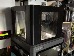
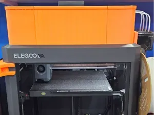
Here are a few key photos of the remix part installed on my ECC1 with Canvas and this riser project:
These screenshots show the finished model being edited in Fusion app:
From the front, straight on with the 4 x PTFE connector holes with the front view of the added PTFE tubes shelf:
Front the front, angled down a bit:
From the inner side:
From above, angled down:
From the bottom, angled up:


Названия используются только для указания источника результата. Polyzon не аффилирован с перечисленными площадками.