
Бесплатно 
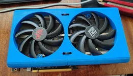
Sparkle A310 Anti-Whine
Printables


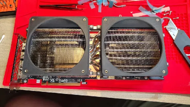
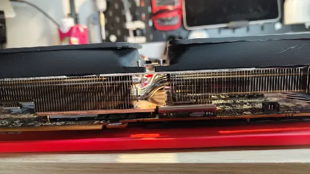
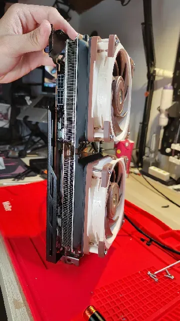
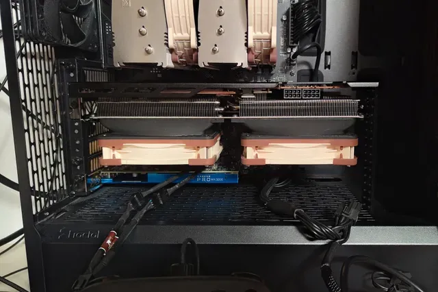
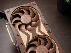
My Sapphire Pulse RX7900XT had an issue with constantly ramping fans and it got to the point I decided to de-shroud it.
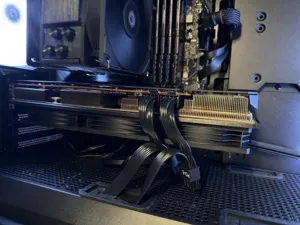
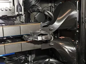
Didn't want to go the zip tie route to I designed a pair of ducts that get mounted directly to the heat sink. Each duct then gets fitted with a 120mm Noctua NF-A12x25.
The Mod is slightly invasive as it requires four 3.2mm holes to be drilled in tho the heat sink frame.
BOM:
- 1x Sapphire Pulse RX 7900XT GPU
- 2x Noctua NF-A12x25 (or any other 120mm fan)
- Y-splitter fan cable
- Thermal Paste for re-pasting the die (thermal pads are optional but when in Rome...)
- The memory dies need a 2mm pad and all other components need 2.5mm pads
- 1x 3d printed duct_rear and 1x duct_front
- 8x M3 nut
- 8x (at least) M3x6mm
- Button heads look pretty good, didn't have enough on hand for all mounting points
- 8x M3x30mm
- 8x M3 washers
- 8x M3 threaded inserts
- preferably 3.5mm long and diameter of 5mm
Printing Instructions:
Ideally you should print the ducts in PETG, ASA or PCTG for better heat creep resistance.
I'm currently running the final prototypes printed in PLA and will keep checking on them as I use them.
Notes for Printing:
- Brim likely required. Unless you have godlike bed-adhesion you should probably use a brim.
- Supports are only needed on the outside of the fan mounting plate (see below)
- 20% infill should be fine
- Orientation see below
GPU DISASSEMBLY
For drilling the holes I decided to fully take apart the GPU and at the same time to a repaste and repad of the GPU with some fresh thermal pads and PTM for the die.
Start off with removing the four screws circled in blue. The two screws toward the middle will be reused later.
Next are two small screws that mount the shroud to the IO shield, the green arrow is pointing at the rough location, I forgot to take a proper picture.
After those it's the cooler brace at the back of the die. One by one loosen up the purple circled screws. If one is close to loosing grip, press down the arm with your finger so it doesn't snap upwards. Repeat until you can remove the brace.
Now it's time to separate the heat sink from the GPU PCB itself. I went ahead and warmed up my GPU with a heat gun set o about 90°C so the paste and pads would be more forgiving. A bit of twisting and some gentle leverage made it pretty painless. In all about 10-15 minutes with some gentle heating and commitment.
!!!BEWARE OF THE FAN CABLE THAT'S CONNECTED TO THE PCB!!!
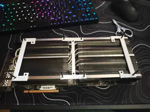
Next is removing the heat-sink from the shroud. I only took a pic afterwards but here is my recreation of what it should roughly look like. Just unscrew the four screws in each corner and it should come right off
For drilling the holes I would advise to remove any thermal pads and transfer them to their respective spot on the PCB. You should also have some thermal paste on hand to re-paste the GPU. Wouldn't reuse the old paste after drilling.
Marking the spots to drill we need the printed ducts with their hardware installed. Each duct gets four M3 threaded inserts melted into the fan mounting plate and four M3 nuts press fitted into their intended holes.
Mount the ducts at the two outside tabs each as shown in the picture on the left. M3x10 bolts are a bit long M3x6 would be optimal. Once firmly in place you can mark the spots on the heat-sink frame through the M3 nuts (right picture).
Drill out the marked holes to 3.2mm, give them a de-burr as well. Make sure to thoroughly clean up any metal chips and dust from especially the copper plate. Leaving any could have them fall on the PCB and cause a short potentially killing the card.
I added some fabric tape along the frame on the two long sides to get a better seal between it and the duct.
After drilling you can now fully mount the ducts to the heat-sink. Here I used M3x6 button head screws which fit perfectly using a regular washer.
At this point I re-padded and re-pasted the GPU for final reassembly. Reversing the previous steps to disassemble the card.





Названия используются только для указания источника результата. Polyzon не аффилирован с перечисленными площадками.