
Бесплатно 
Suntour Command Shifters OBSOLETE
Printables


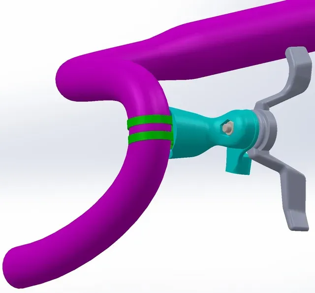
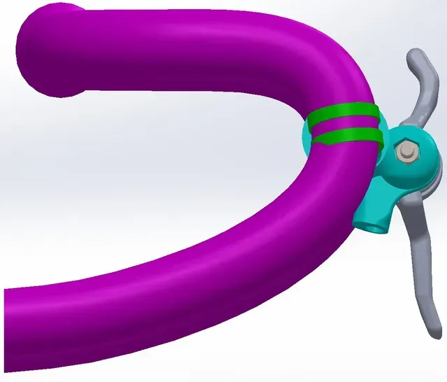

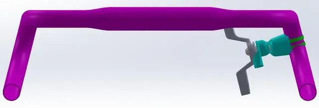

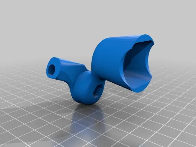
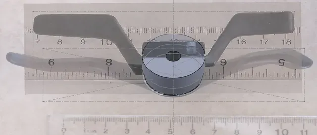



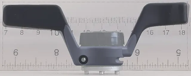
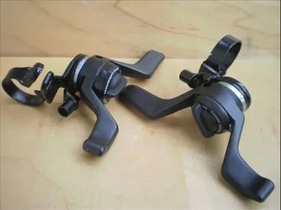


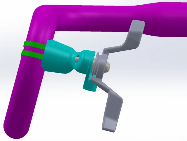
Updated model of the Suntour Command Shifters.
It's currently just a friction lever.
I'm hoping that someone can spare enough time to pick up where I left off.
There are many issues & improvements that I'd love to fix/add, which would first require different hardware, etc.
Modelling the shifters
Centering error
Set up
Now that I had gotten my hands on a genuine pair of the shifters, I could take better pictures & reference those instead of finding ones at odd angles in my previous attempt.
I wanted to preserve the Command Shifters for posterity - & produce a model that did the original levers some justice.
However, even having the actual shifter didn't mean modelling was easy. In particular, there is a lot of error introduced in taking the pictures. The camera might not be exactly parallel to a given face, changing between the top & front shots was probably not 90 deg, lens warp, etc.
In theory, cut-extruding from the top, front, & right planes should get you extraordinarily close. In practice, this was far from the case. This was my first approach when I tried this in Inventor with spline work.
I measured the cylindrical base to be almost exactly 25 mm (+- .02 mm) at its widest diameter. This was in an accessible location, making my caliper measurement very reliable.
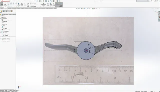
Even when I scaled both images to that verified dimension, & centering them about the central pivot, you can see that there was a significant differential of about 10-15 mm in the overall lever length (which I can't measure reliably).
Conclusion: these might be best scanned with a 3D scanner.
Method
This geometry was some of the most difficult I've ever modeled - I was stuck between solid & surface modeling. The shifters had a number of flat sections, but with several fillets & curves connecting them.
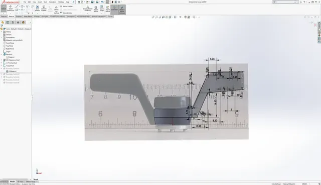
To address the camera issues I had before, I force scaled the levers to match in overall length, rather than prioritizing the cylindrical base match & concentricity. The error I was left to swallow is shown in the "Comparing with the original" section.
I don't like splines since they are difficult to fully constrain; so I tried surface modelling first, at which I'm a real novice.
I had issues with thickening that would've resulted in an inner cavity - although invisible to the outside, 3D printers would not infill that void & the lever would be very fragile. I also tried doing surface modeling with a 3D sketch comprising dozens of caliper measurements. Little errors accumulate, & it wasn't long before the sketch was fully defined & looked nothing like the lever profile.
Ultimately, I used Loft/Boundary bosses (profiles + guide curves), which gave me a result I'm happy with.
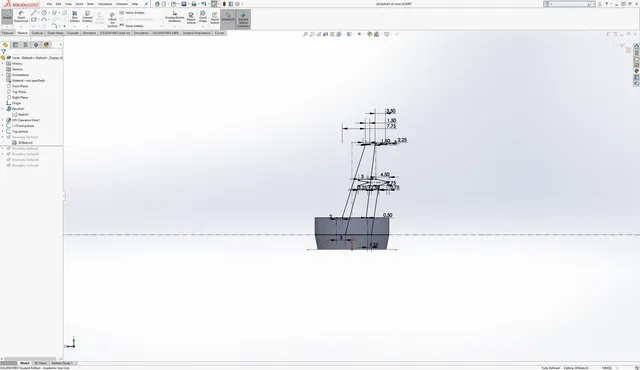
I made two fully defined master 3D sketches, one for each lever, assigning them reasonable dimensions (increments of 0.25 mm) to closely match the front & top pictures I took previously.
You'll notice I did not have a third reference picture for the right. This is because the body/lever interfaces are different for each side. Furthermore, it looks like the original design had some Revolve features going on down there, which I wouldn't be able to accurately reproduce anyways. It came out pretty well regardless.
You can see how atrocious the 3D sketching was in the pictures below. I'm not sure what a better way would've been.
Comparing with the original
It's not easy to tweak the geometry after it's been modeled. The raw Boundary bosses are blocky, & require significant filleting in specific areas, in order , to get the long edge fillets to work.
Solidworks will almost certainly fail to rebuild the Boundary bosses if you edit the driving sketches, meaning you will have to redo the filleting process all over again.
The following pictures demonstrate the final error.
Fixing the errors was time consuming, so I gave up after 1-2 tries, calling it close enough.
Top view error: notice the non-concentricity in the center mounting hole
Front view error: mine sticks out a bit further on the ends.
Future improvements: lever
I can only do so much, so I settled for producing a friction version. The rear shifter I have is capable of switching between friction/index, but that is beyond the scope of this project.
If anyone wants to fix it, by all means.
Two versions of the shifter were made by Suntour. The later version used a clamp band similar to what's on brake levers. Pictures from Velobase.
I have the older version. There is no way (in 2018, at least, without exotic materials/printers), to print a reliable clamp band. As such, I developed my own, which will be later discussed.
Older version
Mounting
Clamp bands
I like the Shimano clamp band method, but unfortunately I don't have a pair to reference.
I do have a similar one likely for a much older brake lever, which much larger & thus forces the lever mount to be much larger at that interface.




Названия используются только для указания источника результата. Polyzon не аффилирован с перечисленными площадками.