
Бесплатно 
Festool-Style Vacuum Hose to Cyclone Adapter
Printables







Cyclone Seperator for Festool Vacuums
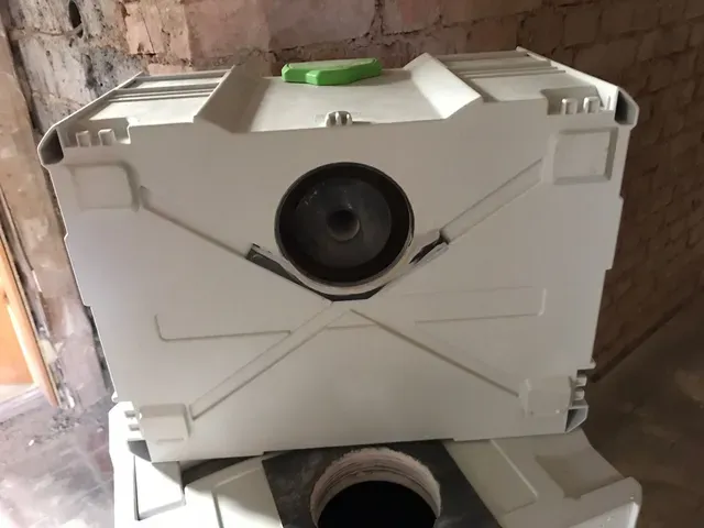
This is my custom version of a cyclone seperator for Festool vacuum cleaners. The goal was to build my own, cheaper version of Festools CT-VA-20, while maintaining the core functionality without sacrificing too much suction power.
Main concept
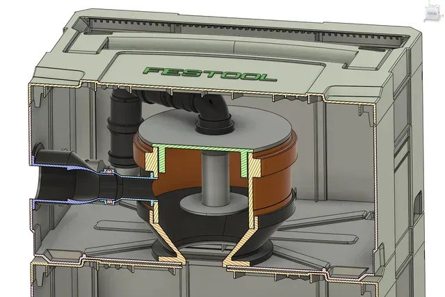
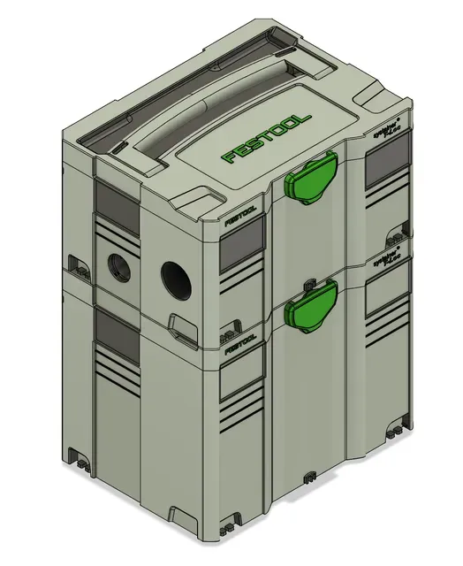
This is the concept I have come up with: Two stacked Systainers (Generation 2, T-Loc) - the upper one (size SYS-3) contains the cyclone and all of the piping, the lower one is a container for the dust and dirt - I used a SYS-4 as it can take quite a bit of dust, but every other size would also theoretically be usable.
Cyclone core
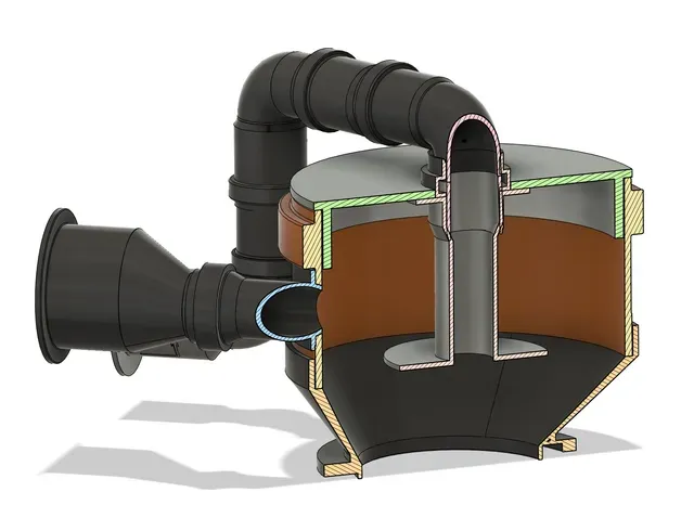
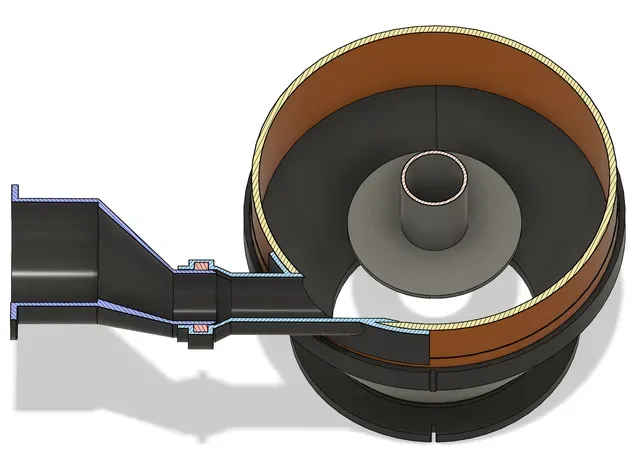
The cyclone core is built from some standard pvc pipes and a few custom printed parts.
The main idea is to insert the cyclone between the vacuum cleaner itself and the vacuum hose, therefore there are two connectors on the outside. The smaller one is to connect the hose from the vacuum (Festool Cleantec connector, grey hose below), the larger one is where a standard Festool hose (57mm connector, green hose below) can be connected, so you can use your existing hose.
Here you can see the different hoses connected, the grey one is going to the vacuum, the green one is going to the tool. I bought the grey hose used as it was cheap, it's a D27x1,0m AS , but 0.75m would also be plenty.
Structure and assembly
To assemble everything you will need to be able to cut a few large holes into the Systainers, two on the side of the top one and another large one through the bottom, which leads into the top of the bottom Systainer.
To aid with positioning the holes, here's a sketch of the position of the center of the holes.
Side view of the upper Systainer
(Click on the images for larger size so you can see the dimensions)
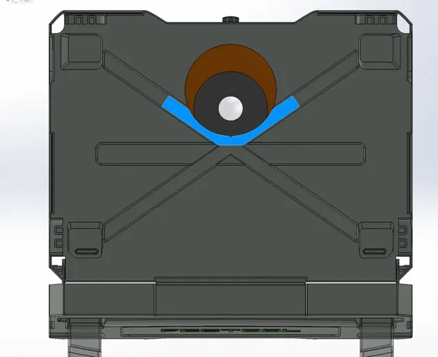
Top view of the bottom Systainer
The dust container
The lower Systainer is the dust container. To make it at least a little airtight, I built a inner box out of some wood with a lid which gets sealed with the help of a EPDM rubber mat by pressing down the lid of the systainer.
The wooden inner box
Also, to get the connection between the Systainers airtight, there is a piece of EPDM mat between them. Because the bottom of the upper systainer consists of a hollow cross, one of the printed parts needs to be glued into the cross so we'll get a good contact surface to seal.
In the following picture you can see:
- The glued-in bracket on the bottom of the upper Systainer - The EPDM mat on the top of the lower Systainer
You might have noticed that there is another wooden part inside the lid of the lower systainer - this is essentially to seal the upper lid of the inner wooden box to the lid of the systainer. The key is that the whole system is as airtight as possible so you'll loose as little suction as possible, that's why I glued a few sheets of wood in there to get good contact to the inner box.
As I did not do a good job here and there are tons of ways to do better than me I won't go in to detail of how I did this - just make sure that your inner box makes good, airtight contact to the lid of the systainer from the inside, otherwise you'll loose so much pressure that the system does not work properly.
Assembly
There are a lot more pictures in the gallery to help you understand how the thing works and looks!
You will need:
- Prints of all STL files - 1x KG 160 double socket ("Muffe" in german) - 1x KG 160 plug - 2x Pipe DN32, straight (length doesn't matter, as we need just a few centimeters) - 2x Pipe DN32, 90° (or 87°) bend - 1x Single DN32 seal for the printed part - Systainer T-Loc size 3 - Systainer T-Loc size 4 (or whatever you want) - Some sort of a rubber mat, i.e. 3mm thick EPDM as a seal - Some wood to build a inner box for the lower systainer - Some glue to connect all the parts, I used Sikaflex 221i. - Begin by drilling the holes with a hole saw. The position and size of the holes in the Systainers can be seen in the sketches above. Also, there needs to be a 44mm hole in the center of the KG 160 plug.
- Glue the cyclone core into the hole in the KG 160 plug.
- Glue the Cleantec to DN32 adaptor to the corresponding hole in the systainer while facing the pipe vertically up.
- Glue the Hose to DN32 adaptor to the Systainer.
- Glue the Systainerbracket to the bottom of the upper Systainer.
- Use the DN32 to Cyclone part to mark the hole which you need to drill or cut in the KG 160 socket, then drill the hole.
- Glue the DN32 to Cyclone part to the KG 160 socket.
- Shorten the DN32 pipes to the lengths needed for putting everything together. You can easily getting the length by looking at how everything should go together, then mark and cut to length.
- Make yourself a wooden box or something similar, that you can put into the bottom Systainer. Just use what you have on hand, you get the idea from my pictures.
- Cut the EPDM mats to size and glue them in position.
- After the glue dried put everything together and enjoy your cyclone!
Simulations
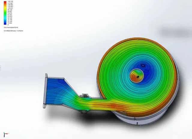
During development of the parts I simulated the assembly with flow simulation software and the actual suction power parameters of my Festool vacuum (CTL-Mini I), the results show that it works as intended. The real world perfomance also speaks for itself, it does really seperate a lot of dust which therefore doesn't end up in the filter bag. Especially for coarse dirt it is really helpful.
Attributions:
Huge thanks to user Ben at GrabCad from who I got the 3D-Models of the Systainers, this made the development process a lot easier. As there is no explicit license, I cannot share the Systainer-files here.




Названия используются только для указания источника результата. Polyzon не аффилирован с перечисленными площадками.