
Бесплатно 
Surface pattern: Spiral Hexagon (Customizable OpenSCAD)
Printables

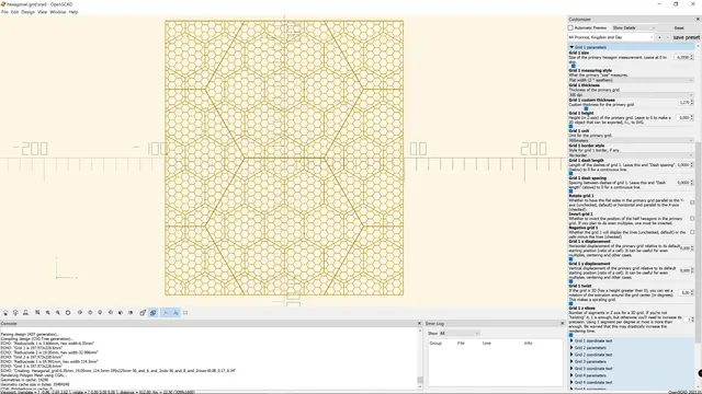

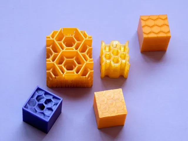

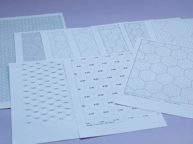
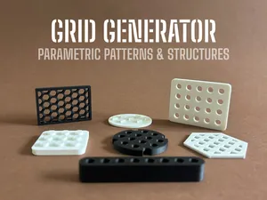
This bundle features an OpenSCAD app to generate 2D or 3D single or multiple hexagonal grids, a JSON preset file, reference and tutorial PDF documents, sample STL and SVG files and PrusaSlicer examples. With this, you can:
- Set up to 5 independent grids - Make negative grids - Include the hex cell coordinates, with full control of positioning, format, etc. - Displace each grid - Use any of different measuring units, like mm, inches, 1/3ds of inch, etc. - Create custom honeycomb infills for 3D printing - Create special effects on top/bottom layers of a 3D printed object - Make “on the fly” battlemats - Create drawing stencils / templates to manually add hex grids to your prints - ...and more! This is the first in a series of many generators of grids, lattices and tilings (and custom infills!). Go checking out this model, the collection it belongs to, or follow me if you want to be up to date with the new ones.
To get it ready to use, download OpenSCAD if you don’t have it, and download both the .scad file and the .JSON file in the same folder; you’re ready to go.
If you want to know more about OpenSCAD apps using the Customizer feature, check out the accompanying “Using OpenSCAD Customizer” PDF, with extensive descriptions and examples, and even some advanced tricks to get the most of your OpenSCAD customizer-enabled models.
Getting started
The basics to make a grid or set of grids are:
- Define the “main area” (width and depth, or X and Y dimensions) in any unit you want. - The grid(s) usually won’t fit exactly that reference “main area”, so you can choose a type of trimming for all the grids, or not cutting them at all and use the main area just as a minimum approximate size. You can also choose a shape for the trimming, other than the default box (square/rectangle). - Set the cell size of a grid in the unit and dimension you want. That is, you can make a grid whose cells are 1 inch from flat-to-flat, or 25mm in diameter, etc. For 2D grids leave the height at 0, for 3D grids enter a value for height. - Select a thickness for the grid. This can be either one of the pre-added thicknesses in DPI (dots per inch), or one arbitrary value by selecting “Custom thickess” and entering it in the “Custom thickness” field of the grid parameters panel. - Modify any other parameters as you wish. The parameters are described in the customizer itself, but you can check the bundled Reference in PDF for more information and detailed descriptions, plus tips and tricks. - Once done, press F6 to render, then F7 to export as STL or go to File→Export to save as SVG (2D) or 3MF (3D), or any other of the supported formats. Tips and tricks
First of all, it’s better if you disable the “Automatic Preview” checkbox in the Customizer, and instead of preview (F5) you use render (F6) to see the effects. It will usually be faster (except if there is a lot of small and high-definition text), but most importantly it will be easy to move and inspect. With the preview, the high number of objects can easily make it lag, which doesn’t happen with the rendered object (which uses CGAL).
Furthermore, it will be ready to export, either to a SVG 2D vectorial file, or to a 3D STL or 3MF file.
You don’t need to use the grids sequentially; that is, you can for instance disable grids 1 and 2 (leaving their cell size to 0) and start working by grid 3.
Note that the size you set is that of the cell and includes the thickness; so, it’s not the useful space. To make an exact useful space, you need to set the measuring to width (2*apothem), add the thickness to the required space, and enter that value as a parameter for size.
The 3D outputs will often be used as slicer modifiers of some kind. This means that you can make big versions, that take all of your build plate width and height, and reuse them often; but they may be visually clumsy to work with (they will cover the relevant objects). For 3D printing, make sure that the grid thickness is set to at least 2 perimeters wide; you can use the “thin wall” measurements as a guide to. But overall, a width of 1.25/1.27 will work well as a “one size fits all”: it’s basically 3 perimeters for a 0.4 nozzle and 2 for a 0.6 one, which is the range for the more usual nozzle sizes.
Exporting to SVG
For a SVG file, you’ll need that all the grids used in the model (those with a “Grid size” greater than 0) have a height of 0; otherwise, they would be a 3D object and mixing 2D and 3D objects is not allowed (because it makes no sense and would cause an interdimensional disruption, as seen in “Doctor Who”).
Render the model with F6 and go to the OpenSCAD menu File→ Export → Export as SVG. You can use the suggested filename in the console to save the file, copying and pasting it in the Export dialog.
Once the SVG file is saved, open it in any text editor and go to the last line. Change the part that reads:
stroke="black" fill="lightgray" stroke-width="0.5"
to
stroke="none" fill="#808080" stroke-width="0"
What this does is to effectively remove the SVG line contour (“stroke”) and set the default color to a 50% gray; the grids are filled polygons, not “lines”. That line would add to the width (but having that in mind, you may want to adjust both the grid thickness and stroke width to have 2-color grids).
Also, some applications (like CNC machining) may require a specific stroke width to use the object in the SVG file; you can set it there. (The SVG units are specified to be millimeters, BTW.)
You can also change the fill color in the parameter “fill”, using SVG notation. The exported grids will be a single object; if you want multicolor 2D grids, you must export them separately and change the color for each one. You can make a combined grid to make sure everything fits, save the preset, and then export each grid individually setting the others to a grid size of 0 (which effectively disables the grid).
You can do any of these operations in a SVG editing program, such as Inkscape, but it will usually be faster doing this in a text editor.
Note that for the SVG files you’ll likely want to use some of the thinner, predefined line widths, measured in DPI . DPI means “dots per inch”, and is a measure widely used in 2D printing (either professional offset publishing or home printers). So, a line with a “300 DPI” thickness will be 1/300in thick, another with “150 DPI” will be 1/150in thick, and so on. Most home 2D printers (or “single-layer printers”, as Ivan Miranda calls them) can comfortably reach up to 1200DPI or more. Using 150 or 75dpi thickness for thickest lines and 300dpi for thinnest gives good results, but that depends on colors used, number of grids, printer status…
You can use the image in Scribus (the Open Source alternative to InDesign desktop publishing software) or any word processor or image printing program. To keep the sizes, make sure that you set the image to 100% and you’re not scaling the print when sending to the printer; set the printing scale to 100% also.
Exporting to 3D (STL or 3MF)
Making a 3D object maybe is easier than a 2D one. You just set the used grid heights to the desired value (greater than 0), render with F6 and export to STL with F7 or the top toolbar button, or to 3MF from File→ Export → 3MF.
3D grid objects are very versatile. You can, for instance, print them in TPU to have an “instant battlemap” over any surface or image; you can adjust the main area to make them tile seamlessly. You can use the grid as a “negative modifier” to any 3D terrain (and there are many programs and methods that allow you to render real-world terrains).
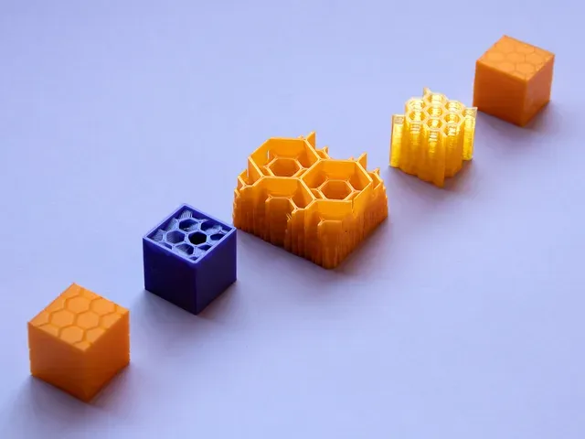
But an interesting and somewhat surprising use of the 3D grids is that of custom infills . There are several techniques that you may use, depending on the complexity of what you want to do, but the procedures are easy. They have a specific PDF tutorial on how to make them and different things you can do. Some are purely for cosmetic effects, but others have structural properties —like a “stepped” or “adaptive” infill that grows progressively thicker or thinner, which can save you material or change the center of gravity of an object.
All you need for custom infills is PrusaSlicer, or any slicer that allows the use of negative volume modifiers and mesh modifiers (such as Cura) and a program that allows hollowing 3D models (like Meshmixer or Lychee Slicer Pro/Premium).
Having z-based multicolor grids is easy; just make them of different height, with each step of enough height so as the colors show well. You can get nice blending effects, though, with small height differences and translucent filaments. You can find some examples of this technique in the pictures of my Geo-parametric coaster creator . You can also check out how the “color blending” works with different layer heights (and how many you do need) with my Filament Swatch (and modifiers) creator . These are also OpenSCAD files with Customizer enabled.
Top/bottom (and side) finish
This is “one weird trick” that you can use for a nice effect with top and bottom layers , and even side perimeters of any 3D model (but top/bottom works best with planes, even if they’re inclined).
Create a grid that fits the object and is 1 or 2 layers tall (say, like 0.2 or 0.4mm). Make it very thin; 0.05mm or less. In PrusaSlicer, select the object, right-click it, select “Add negative modifier”, choose the grid you made, and place it on top or bottom. You can use the “Drop to plate” button right to Z-coordinate in PrusaSlicer to set it on the base. (If you’re not using PrusaSlicer, check your slicer instructions on how to add a negative volume or difference modifier.)
What will happen is that the slicer will understand that the object is “cut” into hexagons at the layer(s) where we put the modifier; but since it’s so thin, the hexagons of the layer will fuse all the same. Now, select a concentric solid infill for the modified layers; you can use a (regular) modifier to affect only those layers we’ve “cut” with the negative modifier. You may want to adjust the Elephant foot compensation, if any, to avoid overdoing the piece separation (which would leave gaps and a first “unsoldered” layer), but in any case having solid layers above the first one or first ones would make them in a single piece.
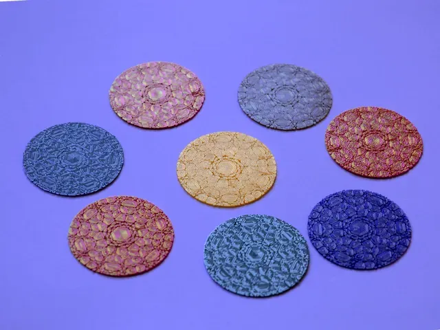
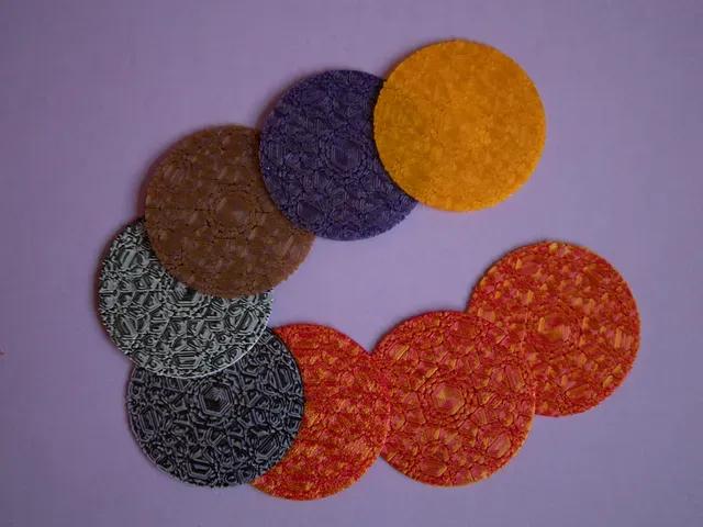
This effect is barely visible on usual opaque matt or glossy filament, but gives an impressive “holographic” effect with silk filaments, and is most visible with multicolor or “toothpaste” filament. Don’t worry about having to buy some if you don’t have this fancy new color style: you can do your own with my DIY Multicolor Filament , which will give you plenty for those first layers.
You can also rotate and adjust the negative modifier to any flat face(s) of your model. With a thin grid thickness, though, the effect may be barely visible, and a bit of tuning is required —it depends on a combination of factors, like your perimeter engine (be it Arachne or other), the nozzle diameter, linear acceleration and others. Basically, in this case you don’t want the “pieces” to solder “too much”. For instance, you might try to make it at least one layer thick; thus, you ensure to display the horizontal lines that are parallel to the build plate. If that results in too excessive a thickness for the other hex lines, try doing a design that has no lines parallel to the build plate, changing the orientation of the grid.
The pattern doesn’t need to cover the whole side . You can do the following:
- Place the object in the slicer. - Add a negative volume to it, covering the area you want patterned. - Add as a new object (not part) the very same negative volume, with the same dimensions, aligned to the main object. - Add the pattern as a negative volume to the object you just added. - Optionally, add another modifier covering just the “inlaid” object, with specific settings. This effect works at best when used with silk or, even better, dual-color filament. If you want just a small “inlay”, you can use the print-on-print technique to inlay objects of up to 0.4mm thick to use several colors without a MMU or Palette devices. Just make non-printable the main object clicking the eye in PrusaSlicer and export the inlay; then make the inlay non-printable and export the main object. Print the inlay first and remove the skirt and purge line; change filament, let it preheating for a while until it doesn’t drip anymore, and print the main object.
The 3MF file “Inlaid base cylinder” is an example of this technique.



Названия используются только для указания источника результата. Polyzon не аффилирован с перечисленными площадками.