
Бесплатно 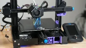
KevinAKASam KlackEnder v2.1 For Micro Swiss NG Extruder
Printables
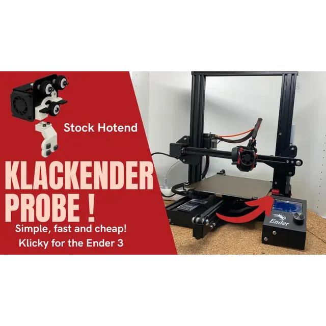


KlackEnder Probe Rev2.1
KlackEnder Probe - Simple, fast and cheap!
What is this about?
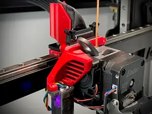
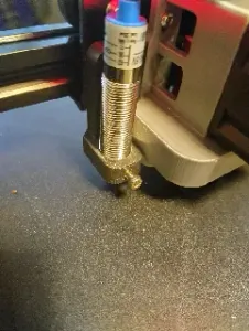
Adaptation of the Klicky / Quickdraw Probe for the Ender 3 and comparable Creality printers. The probe is compatible with all printers that use the X plate of the Ender 3 and cost of the probe is <10€, of which the switch is the most expensive part. The probe is compatible with Marlin and Klipper. Both firmwares work with the G29 command, the docking is done automatically by the printer, it couldn't be easier! Both firmwares add a KlackEnder menu to the display that can be used to dock and undock the Probe. The Bed-Mesh can be created via the custom menu, via the default firmware settings or with G29.
Is it compatible with my printer?
As long as your printer uses a X-Axis plate that's similar to the one of the Ender 3: YES! * *You might have to adapt the parts (slightly) if you're not using an Ender 3 or the stock x-plate. See the Basic-Check section to check the basic measurements and see if you printer is compatible. If not and you really struggle with CAD just ping me on my Discord ;)
Why should I build it?
Well, as with my other mods, the focus is on the best cost-benefit ratio. The KlackEnder is very cheap and very easy to build. No need to pay 40-50€ for a probe that is still affected by heat, takes forever to mesh, and causes a lot of headaches to wire. For the Klack it's: Print - assemble - mount - start printing, that's it. Especially with Klipper, setup couldn't be easier, just use my pre-made macros, copy and paste, hit restart and you're ready for the next print.
Quick Overview:
- Compatible with Marlin and Klipper. Easy setup - firmware changes provided. - 100% automatic probe docking and undocking. - 100% open source parametric design! With the supported CAD file and instructions, it couldn't be easier to customize the parts to your needs! Even if you've never worked with CAD before, I promise you can customize the parts any way you want! - Custom menu to control the probe (not for Ender 3 V2 with Jyers GUI). - The cheapest way to get a fast and very accurate probing ( sample range of 1-2 microsteps (0.000-0.005mm with 16 microsteps) - Easy to install, no soldering, no complicated wiring - Works with all pressure surfaces, not affected by heat, no heat soak required If you have any questions feel free to join the Discordserver .
Parametric CAD Design
I always try my best to support a wide range of possible setups so you don't have to deal with CAD. With this design I have gone one step further: Not only does this design support a wide range of setups, but also the CAD is very easy to adapt for anyone, even if you've never worked with CAD before!
How that? Parametric design!
Parametric design means that everything is based on variables / parameters which you can easily change. The design itself adapts automatically to the changes you made. This may still sound a bit complicated, but trust me, with the detailed instructions I provide, it couldn't be easier! More about that on my [website](https://kevinakasam.com/lets-adapt-the-cad/).
STLs + Bill of Materials + Instructions
As for my Belt-Mod, you can find all needed Hardware, STLs and instructions on my Website:
Click on the image:
Wiring Guide
Since there is no polarity on Switches, it doesn't matter which wire goes where. Just connect the switch to the two marked pins. In the next chapter about firmware changes you will see where to add the pin.
Wiring for the Rev2 is very easy. Simply unmount/unplug your old z-endstop and connect the probe to the z-endstop port.
Firmware Guide
The KlackEnder probe works with Marlin and Klipper. This guide only shows you what changes you need to make to the firmware, not how to modify/upload the firmware itself. There are several guides online for different boards and printers. **You do not have to use the Probe In or Probe Out macros.** They're just a nice to have. The printer will do this automatically when you send a G29.
Klipper
The installation for Klipper is pretty easy. Simply do the changes below and copy the code from the KlackEnder.cfgto your printer.cfg The [gcode_macro G29] does the same like the [gcode_macro AUTO_BED_MESH]. I just added this so you can use the G29 command as usual.
Changes to the existing config:
[stepper_z] endstop_pin: probe:z_virtual_endstop #if you want to use the Prove as z-endstop (You can unsinstall the stock z endstop then. If not, remive the [homing_override]) #position_endstop: 0 #remove this or uncomment it with a # position_min: -8 # set a negative value (minimum as the probe z_offset)
[stepper_y] position_min: -8 #most Ender 3 configs have this wrong. Between the nozzle and the bed is a gap of 8mm (Y dimension) when the printer is homed. If not adapt this and the -8 in the Probe_In Makro). position_endstop: -8 Add new config: Don't forgot to edit your probe Pin
################################## ## Add this to your printer.cfg ## ################################## ##################################################################### # KlackEnder- Settings ##################################################################### # !! Change your Z endstop pin from 'endstop_pin: Pin123' to 'endstop_pin: probe:z_virtual_endstop' # !! Also add in [stepper_y] 'position_min: -8'. Idk why but most configs mave this wrong. For the Stock Ender 3 the homed Y position is -8. [probe] pin: ^PC14 #Probe-Stop Connection on Skr Mini E3 V1.2 z_offset: 0 #Measure per your specific setup x_offset: 4 # negative = left of the nozzle y_offset: 21 # negative = in front of of the nozzle speed: 5.0 lift_speed: 15.0 sample_retract_dist: 1 samples: 2 samples_tolerance_retries: 6 ##[(7x7)-1] / 2 = 24 ##[(5x5)-1] / 2 = 12 [bed_mesh] speed: 300 horizontal_move_z: 2 mesh_min: 8,30 mesh_max: 223,201 probe_count: 5,5 relative_reference_index: 12 algorithm: bicubic fade_start: 1 fade_end: 10 #fade_target: # The z position in which fade should converge. When this value is set # to a non-zero value it must be within the range of z-values in the mesh. # Users that wish to converge to the z homing position should set this to 0. # Default is the average z value of the mesh. split_delta_z: 0.015 # The amount of Z difference (in mm) along a move that will # trigger a split. Default is .025. move_check_distance: 3 # The distance (in mm) along a move to check for split_delta_z. # This is also the minimum length that a move can be split. Default # is 5.0. mesh_pps: 4,4 # A comma separated pair of integers (X,Y) defining the number of # points per segment to interpolate in the mesh along each axis. A # "segment" can be defined as the space between each probed # point. The user may enter a single value which will be applied # to both axes. Default is 2,2. #bicubic_tension: .2 # When using the bicubic algorithm the tension parameter above # may be applied to change the amount of slope interpolated. # Larger numbers will increase the amount of slope, which # results in more curvature in the mesh. Default is .2. [homing_override] set_position_z:0 # Make printer think Z axis is at zero, so we can force a move upwards away from build plate gcode: G90 G1 Z10 F3000 ; move up to prevent accidentally scratching build plate G28 X G28 Y PROBE_OUT G1 X117 Y117 F6000 G28 Z PROBE_IN ##For Dual Z setups only!! (with independent motors, no Y splitters or dual Z port on board!)## [z_tilt] z_positions: 25,117 210,117 # A list of X, Y coordinates (one per line; subsequent lines # indented) describing the location of each bed "pivot point". The # "pivot point" is the point where the bed attaches to the given Z # stepper. It is described using nozzle coordinates (the X, Y position # of the nozzle if it could move directly above the point). The # first entry corresponds to stepper_z, the second to stepper_z1, # the third to stepper_z2, etc. This parameter must be provided. points: 4,96.5 219,96.5 # A list of X, Y coordinates (one per line; subsequent lines # indented) that should be probed during a Z_TILT_ADJUST command. # Specify coordinates of the nozzle and be sure the probe is above # the bed at the given nozzle coordinates. This parameter must be # provided. speed: 100 # The speed (in mm/s) of non-probing moves during the calibration. # The default is 50. horizontal_move_z: 15 # The height (in mm) that the head should be commanded to move to # just prior to starting a probe operation. The default is 5. retries: 10 # Number of times to retry if the probed points aren't within # tolerance. retry_tolerance: 0.01 # If retries are enabled then retry if largest and smallest probed # points differ more than retry_tolerance. Note the smallest unit of # change here would be a single step. However if you are probing # more points than steppers then you will likely have a fixed # minimum value for the range of probed points which you can learn # by observing command output. ##################################################################### # KlackEnder- Macros ##################################################################### [gcode_macro PROBE_OUT] gcode: G90 G1 X245 F4000 G4 P300 G1 Z15 G1 X0 [gcode_macro PROBE_IN] gcode: G90 G1 Z20 G1 X245 F20000 G1 Y-8 G1 Z0 G4 P300 G1 X220 F6000 G1 Z10 G1 X0 [gcode_macro AUTO_BED_MESH] gcode: PROBE_OUT BED_MESH_CALIBRATE #G1 Y0 F20000 PROBE_IN [gcode_macro G29] gcode: PROBE_OUT BED_MESH_CALIBRATE #G1 Y0 F20000 PROBE_IN [gcode_macro Accuracy_Test] gcode: PROBE_OUT G90 G1 Y120 X120 F20000 PROBE_ACCURACY PROBE_IN [gcode_macro AUTO_Z_TILT_ADJUST] gcode: PROBE_OUT Z_TILT_ADJUST PROBE_IN
##################################################################### # KlackEnder- Menu ##################################################################### [menu __main] type: list name: Main [menu __main __KlackEnder] type: list enable: True name: KlackEnder [menu __main __KlackEnder __ProbeOut] type: command name: Probe Out gcode: PROBE_OUT [menu __main __KlackEnder __ProbeIn] type: command name: Probe In gcode: PROBE_IN [menu __main __KlackEnder __AutoBedMesh] type: command name: Auto Bed Mesh gcode: G28 AUTO_BED_MESH Marlin
The installation for Marlin requires some more changes, but I will guide you through this :). These changes are only to get the KlackEnder working correctly. You still need to configure the rest of the options as appropriate for your printer. Support for the KlackEnder and similar probes was only recently added so a current version of Marlin needs to be used. Go to https://marlinfw.org/meta/download/ and download the bugfix-2.1.x . Follow the instructions for downloading, Installing, and configuring VSCode. Before compiling with PlatformIO you will need to setup your config files. Go to https://github.com/MarlinFirmware/Configurations/tree/bugfix-2.1.x/config/examples/Creality find your Printer/board setup and down load the appropriate Configuration.h & Configuration_adv.h. At this point you will want to go through and make the changes below, once completed you should be good to compile and use your printer. We are working on getting Configuration files posted for common printer combinations as well as .bins uploaded with pre-compiled firmware for common setups.
Marlin will now include a probe deploy and stow option under the motion menu when the Mag_mounted probe is defined.
Marlin will now include a probe deploy and stow option under the motion menu when the Mag_mounted probe is defined.
1. Configuration.h
Search for //#define USE_PROBE_FOR_Z_HOMING and uncomment by removing // before #define
Search for #define PROBE_MANUALLY and if not commented out with // comment it out with //
Search for //#define MAG_MOUNTED_PROBE (line 1349) uncomment by removing the // and change the following lines to
#define MAG_MOUNTED_DEPLOY_1 { PROBE_DEPLOY_FEEDRATE, { 245, 114, 20 } } // Move to side Dock / Attach probe #define MAG_MOUNTED_DEPLOY_2 { PROBE_DEPLOY_FEEDRATE, { 200, 114, 020} } // Move probe off dock //#define MAG_MOUNTED_DEPLOY_3 { PROBE_DEPLOY_FEEDRATE, { 245, 114, 20 } } // lift probe up //#define MAG_MOUNTED_DEPLOY_4 { PROBE_DEPLOY_FEEDRATE, { 0, 0, 0 } } // Extra move if needed //#define MAG_MOUNTED_DEPLOY_5 { PROBE_DEPLOY_FEEDRATE, { 0, 0, 0 } } // Extra move if needed #define MAG_MOUNTED_STOW_1 { PROBE_STOW_FEEDRATE, { 245, 114, 20 } } // Move to dock #define MAG_MOUNTED_STOW_2 { PROBE_STOW_FEEDRATE, { 245, 114, 0 } } // Place probe beside remover #define MAG_MOUNTED_STOW_3 { PROBE_STOW_FEEDRATE, { 240, 114, 0 } } // Side move to remove probe #define MAG_MOUNTED_STOW_4 { PROBE_STOW_FEEDRATE, { 240, 114, 20 } } // Ensure probe is off //#define MAG_MOUNTED_STOW_5 { PROBE_STOW_FEEDRATE, { 0, 0, 0 } } // Extra move if needed Probe deploy and stow feed rate can be changed by editing the appropriate lines
Search for NOZZLE_TO_PROBE_OFFSET and change
#define NOZZLE_TO_PROBE_OFFSET { 10, 10, 0 }
// Most probes should stay away from the edges of the bed, but // with NOZZLE_AS_PROBE this can be negative for a wider probing area. #define PROBING_MARGIN 10 to






Названия используются только для указания источника результата. Polyzon не аффилирован с перечисленными площадками.