
Бесплатно 
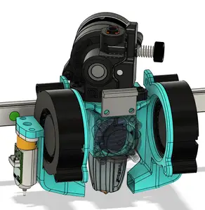
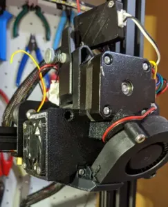
Ender 3 (Pro) - 3510/3010 Dual Fan Duct - Unibody
Thingiverse
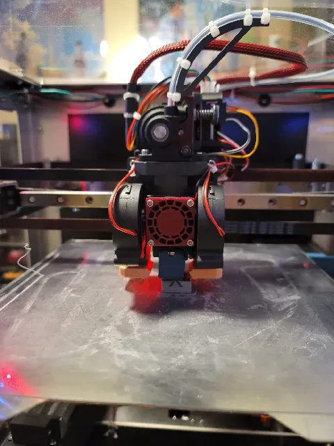


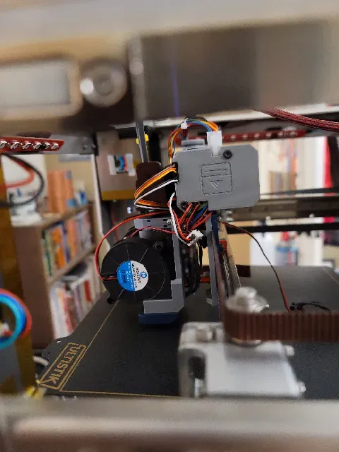


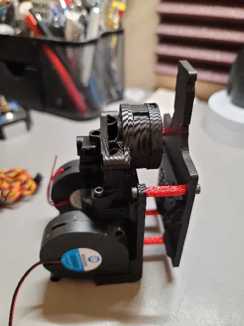


I bought an SK Cube kit but was interested in building my own toolhead, in part to use components I already had on hand (Orbiter 1.0, Dragon hotend, EBB42 Canbus board) and to improve cooling since I print a lot of PLA. I also wanted to stay within the same boundaries as the existing toolhead and not lose any X or Y travel.
The toolhead is also easy to remove for servicing, since it can be removed by disconnecting the umbilical, the X-endstop, and just four mounting screws.
At this time, it's designed around a very specific set of components, but I'd like to expand it to at least cover the much more common Orbiter 2.0, and I am considering modifying a version for the Mellow Libra or Sherpa Mini extruder.
Materials
This toolhead was designed for the following hardware options:
- Extruders - Orbiter 2.0 (not 1.5) - Sherpa Mini, Libra, or Cannon extruder - NikNakTak's Superfly Remix - Hotends - Dragon hotend with extended block (such as the Mellow NF Crazy Volcano or Trianglelab T-Volcano block) or melt zone extender - Phaetus Rapido HF (UHF can be used with an extended BLTouch mount and fan ducts) - 30 mm hotend fan (only a 30 mm fan or smaller will fit) - 2 5015 part cooling fans Optional components include:
- 42 mm Canbus board, such as Huvud or EBB42 - 2 3010 blower fans for extruder motor and Canbus board cooling Fasteners:
- 6 M3x8 screws for carriage plate belt clamps - 2 M3x12 screws for carriage plate upper belt clamps - 8 short M3 heat-set inserts for carriage plate - 2 M3x8 countersunk screws for standoffs - 4 M3x20 female-female standoffs - 4 M3x8 screws to mount tool plate to standoffs - 2 M3x20 screws to for 5015 fans - Mounting screws and heat-set inserts for extruder choice - 2 long M3 heat-set inserts for 5015 fans - 4 M2.5x16 screws for hotend fan - 2 M3x6 screws for BLTouch - 2 short M3 heat-set inserts for BLTouch Fasters for optional parts:
- 2 M3x8 screws to attach Turbiter shroud + Canbus mount - 2 M3x20 standoffs for Turbiter shroud + Canbus mount - 2 M3x4 screws for Canbus board - 2 M3x16 for Canbus cooling shroud - 4 short M3 heat-set inserts for toolboard - 1 M5 short screw to secure Canbus cooling fan Printing
Not every part is naturally aligned for printing in the file but the correct orientation should be pretty clear. Note that the included fan duct requires printing a mirrored copy as well.
Print with whatever material and at whatever perimeter/infill settings you feel is appropriate. I used Prusa PC CF with 3 perimeters and 25% infill for the carriage, extruder, and belt plates, which are the only parts thick enough to matter.
Assembly
This toolhead uses heat-set M3 inserts extensively. Please note that there are some areas where the insert length matters, and others where it does not. The entire assembly can be done with just short 3-4 mm inserts, but in some places the holes are deep enough to accommodate longer 6-7 mm inserts. These as well as the length and type of the screws will be called out below.
Carriage Plate
Eight M3 short heat set inserts should be inserted from the rear to hold the belt plates. The lower six heat sets may be of any length (though inserts longer than 4 mm will protrude through the plate) but the top two must be short, as the upper tool plate spacers mount here. Likewise, the M3 screws for the belt plates may be of any length for the lower six screws, but the top pair must be long enough to protrude a few millimeters from the front of the plate, for the standoffs.
The two M3x8 countersunk screws go through the plate in the countersunk holes near the lower belt clamps, and the entire plate is attached to the MGN12 carriage with the included countersunk screws.
The X-endstop can be attached to the included holes on the left and should correctly trigger against the rail mount. To make the tool plate removable, a connector can be installed.
Tool Plate
Select whichever plate matches your extruder. “Tall” plates are designed to mount the extruder high enough to clear the carriage plate if motor cooling or a Canbus board is being used. If the motor is bare, the “short” plates minimize the filament path by lowering the extruder as much as possible.
The top mounting holes for the extruder and the side mounting holes for the fans may use long inserts. The BLTouch mounting holes at the rear must use short inserts.
Assembly is pretty straightforward. Hotend wiring can either be directed to the rear and up through the space between the carriage plate and tool plate, or up front around the 5015 fans. There are a bunch of zip tie points along the back and sides of the extruder mount for cable management. The fan ducts are snap-fit, but watch out for possible cracking on the fan side if the duct is pushed in too firmly.
It may be best to insert the lower M3 screws before mounting the hotend, as it will be difficult to maneuver in the remaining space. A standard hex key should be able to reach in and tighten them for final installation.
20 mm female-female standoffs are meant to separate the carriage and tool plate, though I believe spacers as narrow as 16 mm may just clear the BLTouch.
The tube bending guide is optional. The reverse bowden is meant to be ziptied to it to take the strain of bending off the tube, but I found the tight radius just impeded filament flow and found no issues just leaving the tube attached on its own without a guide.
Turbiter + Canbus Mount
The included Turbiter + Canbus mount is intended for use with the Sherpa Mini. Note that it will require supports from the build plate for printing, and was designed for the 3010 fan to be mounted from the rear to ease installation. The umbilical is meant to be zip tied to the strain relief post on the left, so make sure to leave enough length to reach across the extruder to the tool board connector. The rather awkward configuration is meant to keep the total height down for those using an enclosure.
For the tool board, two short M3 screws are used to retain the board to the mount, and the two longer screws hold the cooling shroud over it. Without the shroud, four short M3 screws will be fine.
For those using the Orbiter 2.0, a model already exists to combine the Turbiter and Canbus mount from dowjames here . There should be plenty of additional models for those using just the Canbus board without the Turbiter module.
Attributions
Significant credit goes to the below designers whose work I have adapted for this application.
The original Dragon fan duct is derived from Jack Zucker's model here . If you are using a high-flow Dragon heat break, you should use the original model and not the modified one.
The fan ducts and mounts are derived from Declinox's SK Tank mount here . All of the other duct designs in the original will fit the mount, so if a longer hotend such as a Rapido UHF is used, they may be more appropriate than the short ducts used here.
The fan guard was generated using MoonCactus' SCAD file here , and then I just added the SecKit logo to it.
The Canbus cooling shroud is based on BrendalT's design here , modified for the different board arrangement.
Changelog
Jan 21, 2023 - Updated to V2 and moved V1 files into separate folder. Introduced compatibility for Sherpa Mini, Libra, Orbiter 2.0, and Superfly remix extruders, fixed hotend and fan positioning.




Названия используются только для указания источника результата. Polyzon не аффилирован с перечисленными площадками.
Комментарии 0
Загружаем комментарии…