
Бесплатно 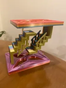
Tensegrity Stair Table
Printables


Summary :
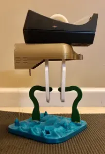
This project aimed to design and create a custom Tensegrity Structure of equal complexity according to our imagination and other inspirations online. Once all parts were printed, we assembled them together to a complete staircase with the landing plate, we tested them to see how they worked and post-processed our parts to have the tensegrity function which should fit in a 20cm x 20cm x 20ish cm cube. In our tensegrity structure, all the components do not touch but experience compression nonetheless.
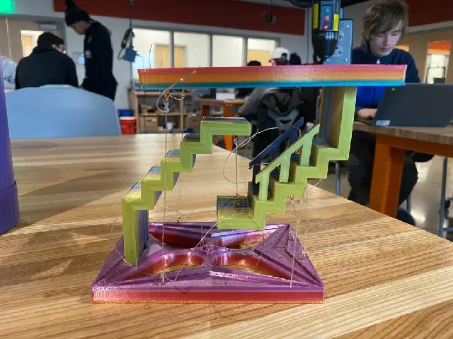
Our project is a 3D printed two staircases connected together and upside down with the landing and railings on the side. We created two staircases, a top landing and a bottom landing, and four railings that would be inserted into each side of the staircase. My partner and I hand-designed each part prior to 3D design to find appropriate dimensions for all aspects of the tensegrity.
With the best print settings and a couple of times post-processing to fit each part perfectly, you will have an amazing non-touching staircase art that two parts facing oppositely using compressed components within a network of chords that are under continuous tension!
40lb fishing line: https://www.walmart.com/ip/Big-Rock-Sports-239370-Monofilament-Fishing-Line-40-lbs-Pack-of-4/53942451
Hooks: https://www.lowes.com/pd/Hillman-Brass-Screw-Eye-Hook/3199937?cm_mmc=shp-_-c-_-prd-_-hdw-_-ggl-_-LIA_HDW_126_Fastening-_-3199937-_-local-_-0-_-0&ds_rl=1286981&gclid=CjwKCAiA2rOeBhAsEiwA2Pl7Q7A7AWkY626UHzdtHH4Khu5PiE4nAmQe5EkHMI4MiYMeFgNDQY_GYRoCCUIQAvD_BwE&gclsrc=aw.ds
Overall Dimensions were 15 cm long and 15 cm high when all put together.
Link to my partner's page: https://www.printables.com/model/374986-tensegrity-stairs
Post-Printing :
How We Designed This Lesson Plan:
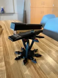
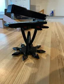
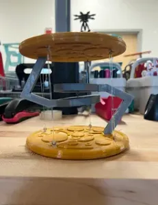
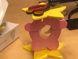
Problem Statement: With a partner, you will design and create a single custom Tensegrity Structure of equal complexity or greater as the tables depicted above (as determined and approved by the instructor).
Constraints:
Design MUST take advantage of print orientation to create the strongest structure possible. Each piece should fit inside of a 15cm x 15cm square. When constructed, the final structure should fit in a 20cm x 20cm x 20ish cm cube. Parts MUST begin with a constraint box, center-rectangle centered on the origin. No single dimension can be smaller than 0.25cm. All “plates” MUST have a thickness between 0.75cm and 1.00cm. All “beams” should have a thickness of 1.00cm. Engravings should be cut to a depth of 0.07cm. Dimensions should be detailed but efficient. Sketches should be fully defined when complete. Parts MUST contain zero error messages. Structures MUST be assembled virtually before 3D Printing to ensure successful models. Screw hooks and fishing line will be provided for attaching your pieces.
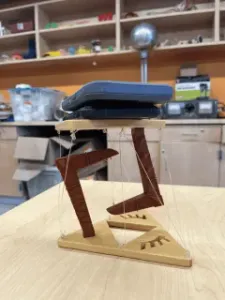
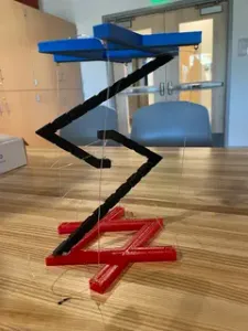
The inspiration was this image:
Beginning Stages:
In the beginning, we started to sketch the general outlook of the tensegrity structure:
After that, my partner started to design the staircase and the railings: she created a constraint box with dimensions of 10.18cm(vertical) by 7.4cm(horizontal) and a vertical line that is 3.73cm long. And by using the perpendicular guidelines, she created a horizontal line of 1.33cm at the bottom of the first line and a vertical line of 1.33cm at the bottom of the second line. Repeat the above steps more times, and another more horizontal line at the end that is 2.08 cm. This is the bottom side of the staircase, and there should be 5 horizontal lines in all.
Then, offset this staircase to 0.75cm and turn off the cap ends. Where the cap ends would be, draw a line to connect the staircase and its offset.
For the railing notches: On the second step from the top, she drew a square with sides of 0.54cm. This square was 0.25cm from both corner edges of the step on both sides of the step. Later, extrude cut these squares 0.5cm down.
For the railings:
By creating a vertical line 2.5cm and a perpendicular line 0.5cm and then another 2cm vertical line off of that line. This should result in a U-shaped structure. Create another U-shaped structure, this time with dimensions of 2cm, 0.5cm, and 1.5cm. Repeat those steps and there should be three independent U-shaped structures. Put the three structures diagonally down from each other, with the smaller one in the middle. With a line, connect the first 2cm line to the 2cm line of the next railing. Repeat this step again until all U-shaped structures are connected by 2 diagonal lines that are colinear. On the same colinear lines as the ones created in step 13, continue the line by drawing two 0.5cm lines, one off the leftmost 2.5cm line and another off the rightmost 2cm line. On the two lines, draw perpendicular vertical lines up from the ends of the line. Connect the top of those two lines with a line that should be parallel to the colinear lines. Extrude this sketch to 0.5cm.
The bottom left one was our final sketch.
I designed the sketch of the top and bottom(same):
We don't want a simple design of the plain, flat top and bottom, so I made the design more of a complex and art add-in.
I sketched a 15cm x 15cm square and with the center point of the square, I created an 0.74cm radius circle and another 1.25cm radius circle by using the same center point. Outside the 1cm radius circle, disturbing the circle circumference into the same four parts, and on each part, sketch two arcs that are 2cm high and correspond to the center point of the square that is opposing side to each other. Create a rectangle(1.5cm high and 6cm long) that is inside and 1.5cm far away from one side of the big square and it should be centered. Find the midpoint of one side, and draw three construction lines that are 4cm, 2.5cm, and 1.5cm high. On each point, scratch out two lines from the top point to each side’s endpoint which forms three triangles. Repeat the last step and create other three triangles on each side.
We designed each part on SolidWorks and eventually put our automaton together in an Assembly. We had three versions to 3D print out the best structure that could reach the tensegrity:
Version 1.0:
version 1.0 printed parts:
After the first version was printed, we found many problems. The main issue was that one of our base print designs had a cutout that was too wide, which caused it to look like the stairs to the platform that we originally wanted to not be able to stand and hold. This also hindered our ability to connect the stairs to the base, so we had to use a lot of hot glue to connect the two to maintain balance. In the figure, the circled part shows the hot-melt micelles required to stabilize the structure and achieve tensegrity. Secondly, the holes in the stairs are too narrow, so our railings cannot be completely inserted, and we had to use sandpaper to sand the sides of the railing to make it smaller in size. So, we have to make sure railings fit into the correct holes, then take the railings off for more space to work.
The improvement we are thinking about :
I and my partner decided not to have the cutouts on the 2.0 version, and we would eliminate the space between the stairs and the side of the inside hole by making the hole smaller. Instead of three contact surfaces, the new one would have four contact surfaces. The length will be decreased by 0.02cm, and the width would be reduced to 0.79cm (thickness of the stairs + 0.04cm).
This rectangle hole will be reduced.
To save material, by making the square top narrower top and cut the width of the stairs by 1.74 cm (the new width will be 5.28 cm).
The last change would be to enlarge the stair holes by 0.04cm on each dimension so the railings can fit inside.
Version 2:
Instead of all brown color, we changed to the rainbow color, which made the whole look more attractive to the viewer. And below were all parts printed for version 2.0.
The 2.0 version has been greatly improved, the base is rectangular, and the stair hole is smaller, but the whole base is also thinner than we expected, and because of the thinness, the base and the stairs cannot be balanced when connected, because one is too light to support the stairs' weight. Another change is that the two bases now have holes, which can save time to find the position of the holes when splicing in the later stage. To save material, both bases have four cutouts.
The staircase couldn't fit into the hole:
We put some hot glue in both bases' holes to maintain each staircase was standing tightly in the hole.
The modified railing fits perfectly into the new stair holes. But the stairs wouldn't fit in the stair holes, so we spent the entire class sanding down the stairs and clipping the inside of the holes with broken wire cutter blades and the tip of a hot glue gun. The thinness of the bottom made us spend a lot of time sanding.




Названия используются только для указания источника результата. Polyzon не аффилирован с перечисленными площадками.