
Бесплатно 
DIY Brushless Magnetic Turbo Stirrer
Thingiverse


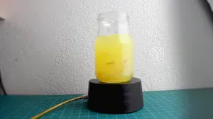
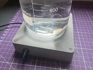
This is a DIY magnetic stirrer I designed to upgrade my old "pc-fan-approach"
Things needed:
1x 300mm GT2-belt
2x 608zz or 608rs bearings
1x M8x40mm or M8x50mm bolt
1x M8 Locknut
1x 2212 Brushless motor (I used an A2212/13T with 1000KV) with 4xM3x5mm Screws
1x ESC for brushless motor
1x (recommended) Propeller mount (used to mount the pulley on the motor)
1x (alternative to above) M3 Screw/Grubscrew + M3 Nut (about 6mm long)
1x (recommended) 40mm 12V fan with 2xM3 screws (length depends on your fan)
8x (recommended) 8x3mm disk magnets
1x 12V source that can drive your motor + fan
1x (optional) A metal plate 100x100x1mm (ideally a non magnetic metal like copper or aluminium)
Printed Parts:
Note: The Pulleys used in this design are based on the "Parametric Pulley for toothed belts in OpenSCAD" by "0scar" ( https://www.thingiverse.com/thing:2758711 )
You need the "MainPulleyV2", the "BaseSkeleton_Lite" and either the "motorPulley" or the "motorPulley_screwMount" the latter is untested.
For mounting the magnets I included "MiniMagnetInsert8mm" whih I use with 4 mini 8mm disk magnets each.
The MainPulley contains 8 holes where you can place the inserts according to your "stir fish" (is it called that?).
You can print two "SidePart" and a "BackPart" to hold the metall plate above the stirring mechanism. It is pretty solid, I tested it with up to 500g load and there were no issues but it may depend on the material used.
Assembly:
- Free the holes in the printed parts (the small layer should help with bridging). There are 5 holes where the motor should be placed (4 for the screws and 1 from above for the motor axis) and 1 hole for the M8 bolt. - Mount the Motor with the leads out to the side on the BaseSkeleton with 4xM3x5 Screws (mine came with the motor) - Mount the motorPulley to the axis of the motor - Put the bolt through the MainPulley, then a 608 bearing, then the BaseSkeleton and another 608 bearing. - Secure the assembly from step 4 with the M8 locknut. (Not too tight, it needs to be able to spin freely) - Put the GT2x300 belt on - Insert your magnets into the inserts and place the inserts in the desired position on the MainPulley - (optional) Screw the fan into the two holes behind the motor, so that the motor is cooled by the fan - (optional) With a sharp knive carefully remove the supportlines in the top slots of the "SideParts" - (optional) Slot the two "SideParts" into the slots on the bottom of the BaseSkeleton - (optional) You can now insert the 100x100mm plate into the side pieces - (optional) Gently push the "BackPart" into the slots of the sides Software
For the moment I use a very basic Arduino snippet to control the speed with the serial terminal.
You could basically use anything you want, like an RC-Remote or anything that can tell the ESC to spin the motor.
Just for completion I added my Arduino code. I take no responsibility in it destroying something because it is slow.
You can send it a value from 0 to 180 (no CR or LF, 9600 baud) and after a read-timeout it will start accelerating or decelerating to the target speed (0 is instant).
Connect the ESC-signal to Arduino-pin9 and ESC-GND to Arduino-GND.
Notes
The software will change hopefully.
If you want to use other magnets I included an OpenSCAD template for the Inserts that you can use as a starting point.








Названия используются только для указания источника результата. Polyzon не аффилирован с перечисленными площадками.
Комментарии 0
Загружаем комментарии…