
Бесплатно 
Sonic RC Delta Wing
Thingiverse
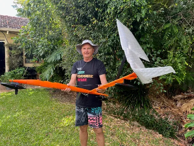
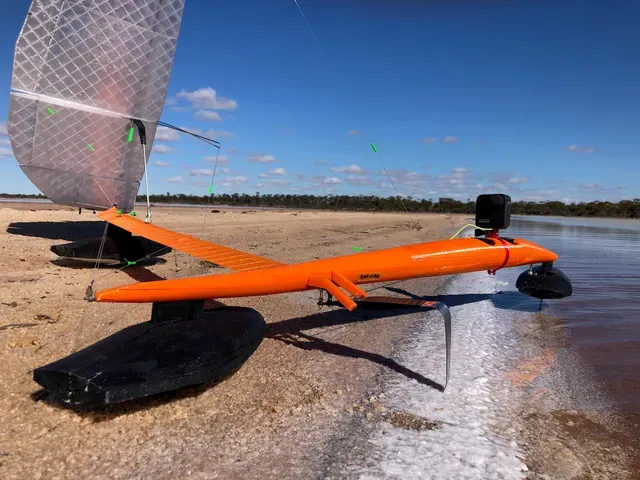



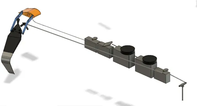



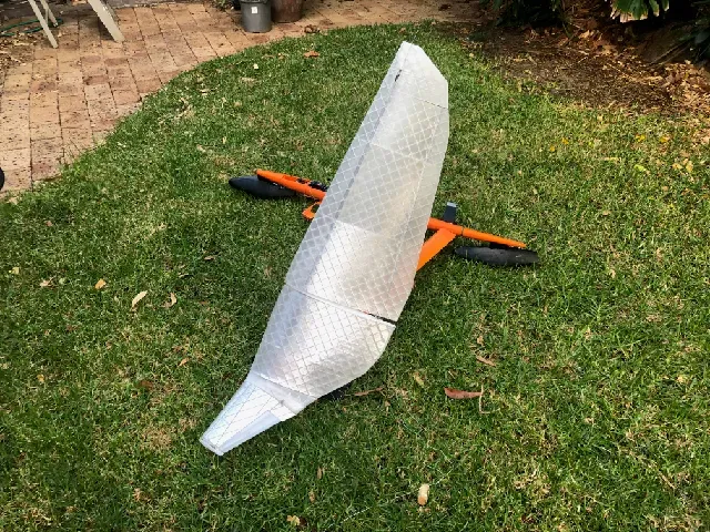
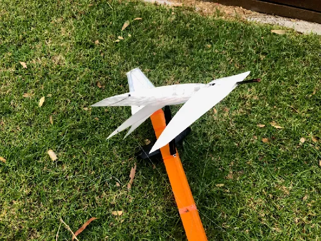
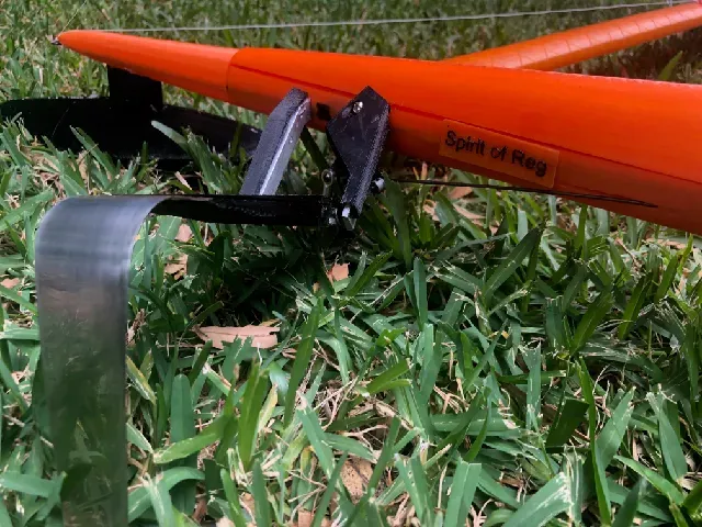
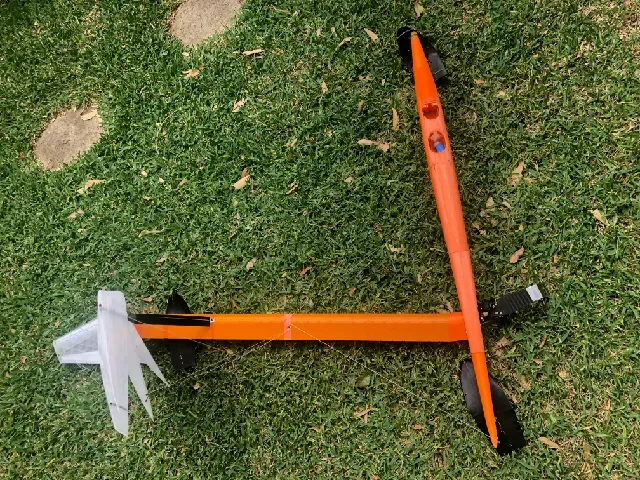
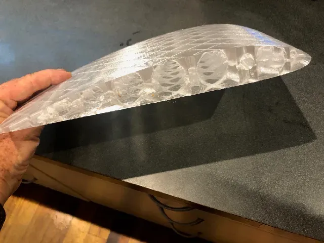

Sail Rocket 2 set the current water speed record for wind powered craft in 2012 of 68.33kts peak and 65.45kts over 500m. Paul Larsen was inspired by the design of Bernard Smith in 1963 to build a sailing craft like an aeroplane that “comes down to grab the water”. Bernard thought the main application of such a device was a submarine hunter as it could travel silently long distances at 40+kts without any need of fuel.
It essentially is an Ekranoplane that flies in ground effect just above water but powered only by the wind. Unlike other sailing craft the stronger the wind the more stable it becomes…up until it breaks. The colour was inspired by the Bell X-1 (first aircraft to break the sound barrier) as this vehicle was designed to smash through the 50kt barrier which existed at the time.
Short video on Sail Rocket 2, Paul Larsen on the record setting run and the build so far
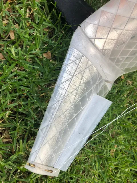
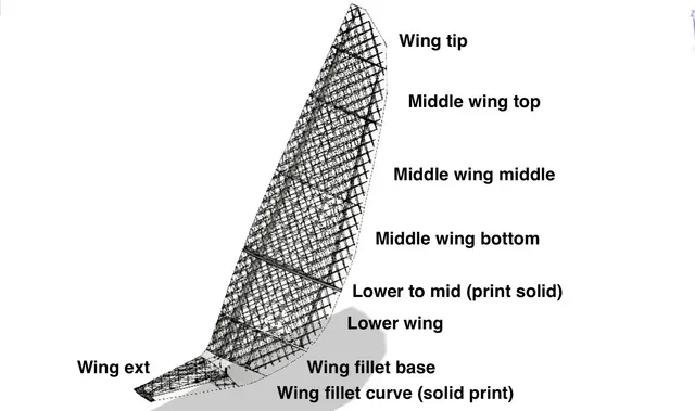
I was planning on a 1/5 scale model as Paul Larsen did prior to making the full scale version but decided to make a 10.5 scale to work out the basics of the design. Why 10.5?, this is the absolute biggest scale that can 3D print the sail aerofoil in one piece on my Prusa i3 MK3S.
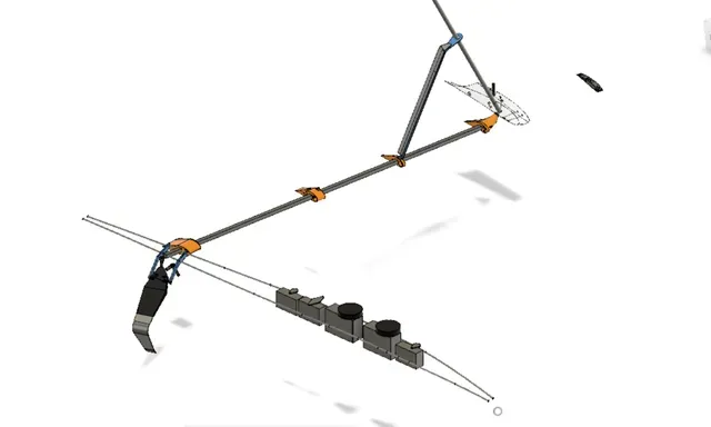
You can view and rotate/explode the model here (note it takes a few minutes to load) which may help explain how it all comes together. Use the explode tool or the animation to pull model apart. You can drill down into the components to see where they go but please note all components are listed here including the old outdated ones https://a360.co/40eg5Ej
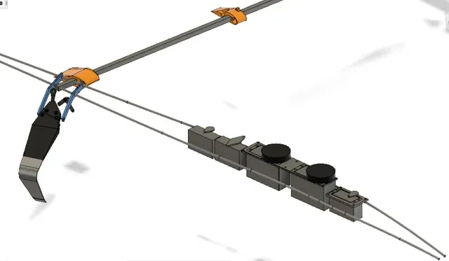
Edit: Major revision: Apr 13th. The original design tried to make two giant winch servo's built for ¼ scale sailing boats fit inside the fuselage. This in turn led to lot of non ideal compromises and was difficult to print. (i.e. the Cockpit was two pieces with holes through it, the sheeting lines ran through the electronic bay lid, the lid didn’t have full length splash seal etc etc) It wasn't intended as a finished product as was just roughing out design for the larger 1/5 scale. However I wasn't happy posting something with so many issues so I redesigned the fuselage to suit standard sized (40mmx20mmx40mm) winch servo's and fixed a bunch of errors found during the first build. Also got rid of the S curve flap control to replace with \ micro servo (or linkage system). The result is a much cleaner and stronger print and far more functional. Way better for a scale model print at the very least.
Lots of words below but build video here to show how it comes together
Despite living in the third windiest city in the world there hasn't been a breath of wind here for weeks and no sign of any coming so can't get this bad boy out on the water….
There is also the additional of a compression system which puts the entire fuselage in compression which greatly increases strength. This is important especially at nose and tail sections where the front and rear float attach as the whole model is around 1160mm long but standard carbon rods come in 1000mm sections.
Whilst I have finished the design and printing it may take a few days to upload and document all the changes so if you are making/or planning on making this, check back often.
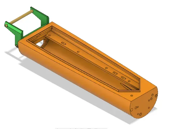
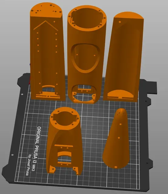
Anything that has been changed or added now has a prefix V2. For the fuselage, V2 parts are totally NOT compatible with the previous parts. The foil fuselage(2) parts print horizontally but the rest of the fuselage prints vertically. Tail bits can print vertically or horizontally. The main fuselage parts are designed to be printed in a certain orientation without supports (see the screen shot). I have included print files for all the major components for i3 MK3S for PETG. The print files all use the fastest possible settings i.e. 0.3mm layer height draft
Changes as follows, starting from the nose, working backwards:-
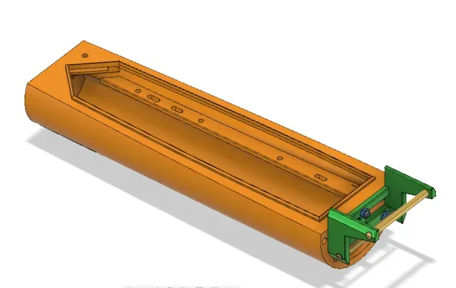
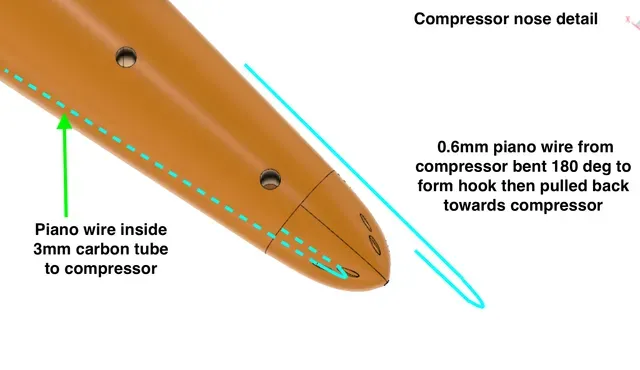
V2 Nose - now one part, 4 embedded nuts and includes holes for compression lines
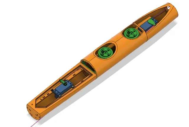
V2 Front servo bay and lid, integral servo mount, better connecting bolt layout
V2 Cockpit, now one part.
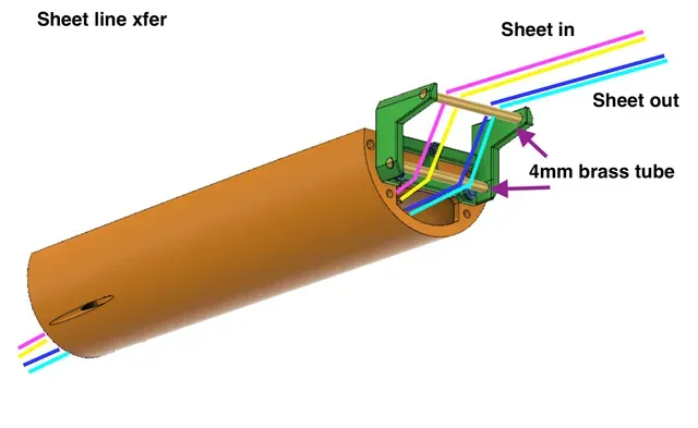
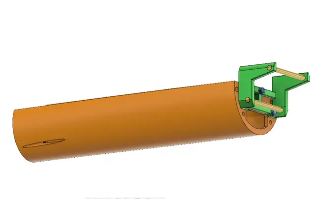
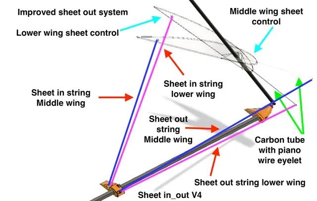
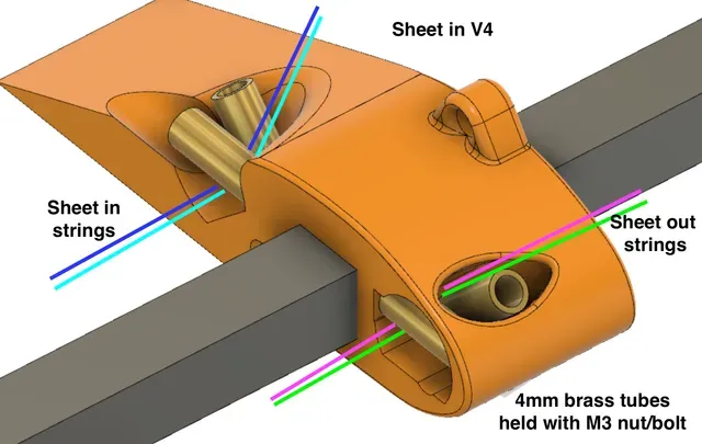
V2 Electronic bay, clean and versatile layout and full lip for splash protection. 4ea 20x3x5mm rare earth magnets latch to Lid with same amount of magnets. Addition of antenna hole. A sheet line deflection mechanism bolts to the front which integrates into cockpit. This routes the sheeting lines so can remove the lid easily. (The alternative is to mount the winch servo's upside down with spacer plates). There are also two sort of hooks at the rear, the intention of these is to hold rubber bands that will keep the sheeting lines in tension when lowering the sail for transport.
V2 Foil body bottom, no flap hole, simplified capstan/bollard system. press fit nuts to bolt to Ebay, Made as long as can print on Prusa i3 MK3S horizontally. The Foil body top now bolts on from underneath.
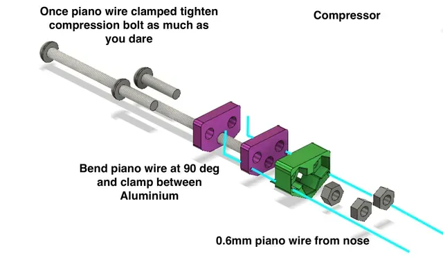
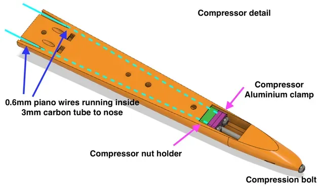
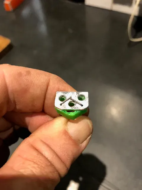
V2 Tail, this is where the compression mech sits. This works as follows. Two 0.6mm piano wires run through the 3mm carbon tube from the nose to the compressor clamp. (Note you have to splice the piano wires inside the carbon tube as they typically come in 80cm lengths…else head to your local piano tuner to get longer lengths) possibly use guitar string instead.). From the compressor clamp a M3 bolt runs to the tail tip. Tightening the bolt puts the piano wire (and bolt) in tension, thus compressing the entire model and mashing all the print layers together. (This is a technique which really works I use for making 3D printed windsurf fins which vastly increases strength..see my other models). Totally can skip this whole thing if don’t need the extra strength.
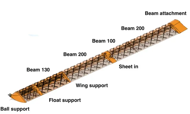
V2 Beam attachment, larger hole for running micro servo wires, slight change in sheeting hole arrangement, fixed hole size.
V2 Ball attachment, clean design, now just one hole for micro servo (or linkage)
V2 Wing Base Fillet, corrected errors where external edge didn't join in places. Extended front strut which now interfaces to the V2 Curve fillet
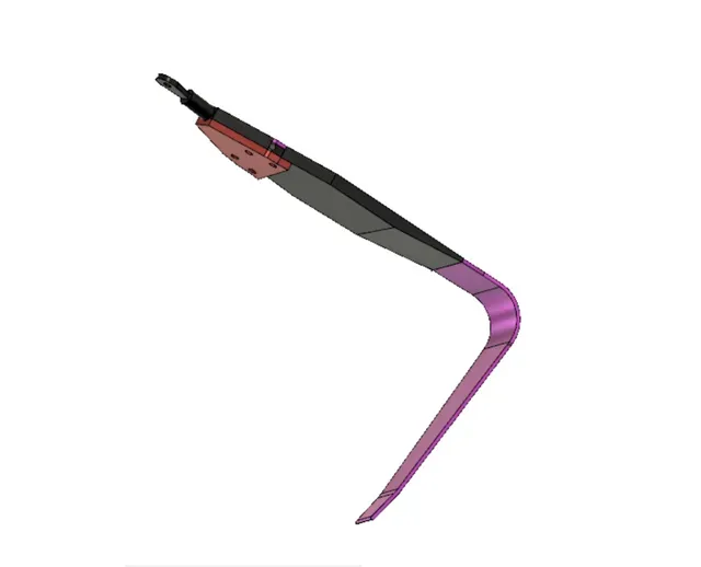
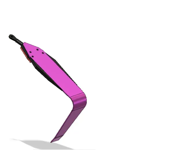
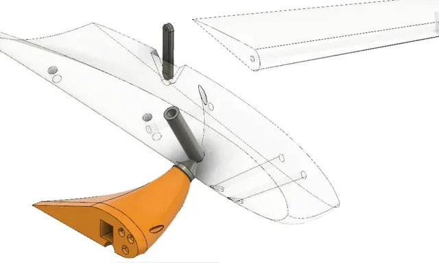
V2 Curve Fillet (Solid print), now has micro servo bay for flap, recess for flap horn (so no need to cut Wing Ext), wire channel and connects to Wing base fillet with additional carbon tube (front, where the anti torque lines attach). Designed for Emax ES 9051 water proof servo which fits.
V2 Wing Extension, remove errors where external edge didn't connect at places.
V2 Wing tip, remove sheet out stuff and extend holes for carbon tubes and flap rod
Since I have ordered but not received standard winch servo's I made some dummy servo's to test mech. Some that just want to make a scale model may not want to buy proper servos.
Loose the original anti torque bar. The real machine just uses ropes/wires which allows the sail to be lowered.
V2 rudder horn, this is slightly tapered to give clearance for the lid. Use a standard servo horn filed down or shorter as stronger alternative
V2 Leeward Float support. This now integrates the float strut and anti torquer stuff as was a weak point.
V2 Anti torque. The Anti torque mech needs to keep the Wing extension, fillet and wing tip etc at 6 deg toe in to foil as far as real machine/Bernard Smith design. Have made adjustable as model scale may be slightly different. In order to lower the sail, the anti torque/mech needs to be flexible. I went with 1mm stainless rope (since I had lots lying around). The wire is held firmly in place inside the 3mm carbon tube with small piece 2mm x 0.45mm WT Al tube ( a drop of super glue to be sure). A knot in the stainless rope is simpler but you loose a little of the carbon strength inside the curve fillet. Small tenth of 3.5mm brass tube stops the carbon splitting. Wire then goes to the wire holders. The adjustable screws need to be as short as possible so don't interfere with sail lowering. Can adjust basic wire position by pulling the wire through wire holders that lock in place once in tension.
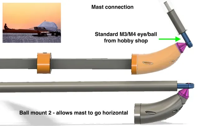
V2 wing support. In order to quickly lower the sail I went with a 4mm clevis system that locks onto the wing support. The main support is a 4mm stainless rod with M4 thread on one end that I salvaged from an old printer. It fits onto the mast holder snugly and can adjust length with spacers inside.
To follow, I noticed the struts are for the 30% larger floats. Need to adjust slightly for the scale floats but if I didn't tell you, you probably won't notice.
I noticed after reading Paul's Blog and looking at videos of real machine in detail the rear float includes a retractable skeg to assist getting machine moving initially. However, I couldn't see this on any models so it may not be necessary. If needed in future I plan to just duplicate the front float and include a locked rudder.
Included DXF files of Aluminium foil supports and Stainless Foil shape before bending.
Note: due to number of components, highly likely I have forgotten to upload something so if appears anything missing, please let me know.
Disclaimer: This is not a sailing boat for lazy Sunday’s in your local pond. It is a high wind specialised machine that only sails in one direction. Judging by other models, if it goes at all it is likely to go very fast and will be quite dangerous to anything in its path. Please use common sense and don’t hold me accountable for any damage you may cause. It sails a Starboard tack (wind coming from right) to match the real machine and the majority of speed sailing spots in Southern hemisphere: Walvis Bay (where the record was set), Luderitz, Lilacs, Chook Pond, Rsoles, Pink Lake etc
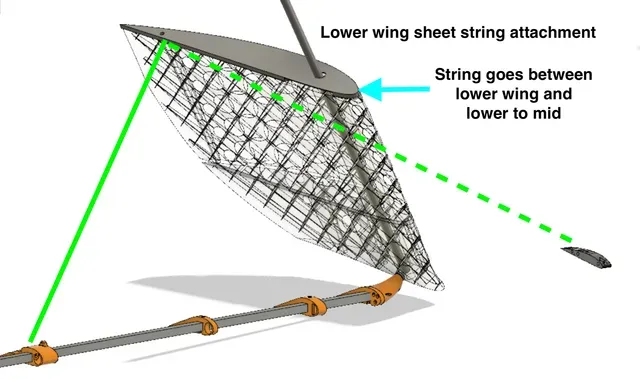
Update Apr 22. Added line adjusters to change length of tie down string and sheeting strings easily. Seems to work well with the 9Kg fishing line I am using. Feed the fishing line in and out through all but one of the holes, create a loop then back through last hole and tie a surgeons knot. Removed unneeded hole in tail bottom (V2.2), modified sheet in slightly (V6)
Apr 24: added Front servo bay + lid front tie down screw (50mm M3) to lock lid tight. V2.2
Apr 25: middle wing sheet control outside tie down hole is in wrong position. Updated but seems need to shift the whole thing 1mm forwards…this version better than before but could be better.
Apr 26: Middle wing sheet control had sheeting hole in wrong spot, corrected with V2.3. Thinned mast holder slightly to give better clearance. Correct some weird offsets in model..still some remaining..doesn't effect print
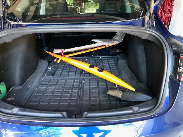
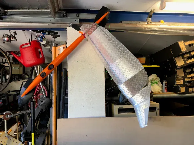
Apr 30: Added storage/transport clamp that holds the wing securely in lowered position so can fit in vehicle/hang out of the way. It uses the wing support with its clevis to lock the wing and so you don't loose it. It is 3 parts Beam, Front and rear clamp held together with 4e 10mm M3 bolt




Названия используются только для указания источника результата. Polyzon не аффилирован с перечисленными площадками.