
Бесплатно 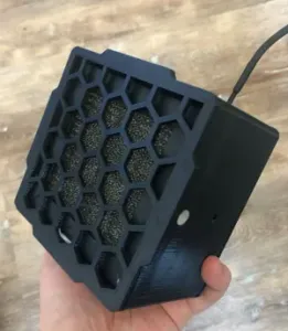
FAN FILTER (Built For Flsun SR)
MakerWorld

DISCLAIMER: Make this upgrade at your own risk, always do your research and make sure to solder in a well ventilated area and always make sure to have the power turned off on the printer before installation!!!
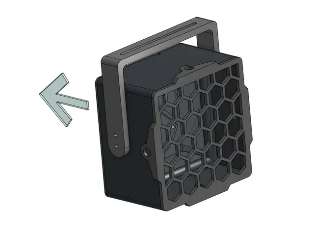
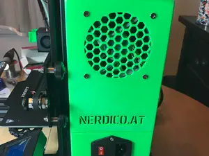
Description: Cover and magnets are optional since the filter is friction fit into the case. Uses the Noctua 80mm fan as well as the included screws to mount the fan to the case. Uses M3 screws for the handle and for the back plate. Parts list at the bottom!
Everything is built to be compatible with my enclosure. Link here: https://www.printables.com/model/405015-flsun-sr-enclosure
Instructions:
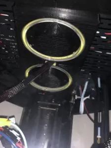
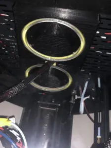
You only need 1 ring for good lighting (but I used two since the lights come in a pack of 2), the print uses at least 2 M4x8 screws for mounting each of the lights.
The Board
Notice below that the board that my Flsun SR came with is the robin nano v3.1. However, some SR's may not use this board so make sure you do your research to see what type you have what connector type you need.
For this board, there is only one 12/24V output on the top left we can use. I have split this source into two outputs with a separate buck converter each (one for my led lighting: https://www.printables.com/model/440181-flsun-sr-lighting ). For this project, you will only need one buck converter so ignore the second one that I will be using.
The Switch(s):
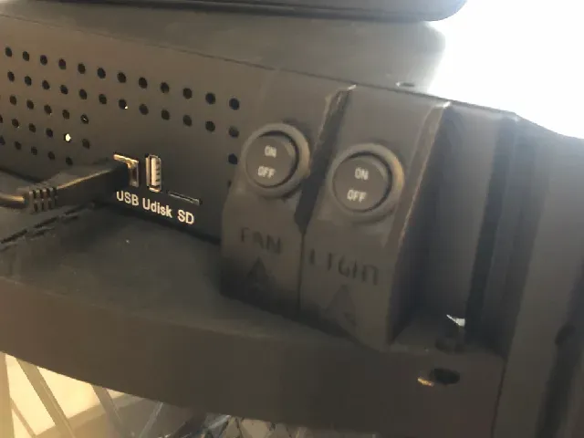
There are two switches shown, but you will only need to look at the fan switch, ignore the other one unless you are making the lights as well. We will be using the grills on the printer as screw holes for mounting the switch with M3 short screws (Only need 1 screw). INSTALL THE SWITCH BEFORE SOLDERING. IT IS NOT POSSIBLE WHILE SOLDERED TO CIRCUIT!!!
Fan Soldering
The Noctua 80mm fan (link at bottom) comes with two extension cables. We will use one of it and snip off the female end and replace it with a female JST connector. We will be connecting the red and black wires only and tuck away or cut off the yellow section. Put the sleeve back on before soldering the two so you can have a clean look.
Circuitry and Soldering
Below are a few images (it may be confusing so I added a (not good, sorry, but hopefully readable) schematic of the circuit). Again the 2nd buck converter is for the LED project so ignore that. The input comes from a female JST connector that goes from the board into the buck converter. The output connects the switch and then outputs to a male JST connectors which then connects to the previously soldered on female JST connector. Optionally use the buck converter to adjust fan speed (You can see a small Philips screw that can be adjusted). BE CAREFUL NOT TO SHORT THE CONVERTER OR SPARKS WILL OCCUR AND ALWAYS BE CAREFUL AROUND HIGH VOLTAGE SOURCES.
The Fan
Uses a Noctua 80mm fan with a 4x4x1 inch HEPA/carbon filter The fan simply slots into the case and is screwed to the backplate using the included screws. The backplate is then attached to the case using M3 screws with the filter friction fitted to the front. There are also optional magnet holes for the optional cover print if you want to have a cleaner design.
Installation:
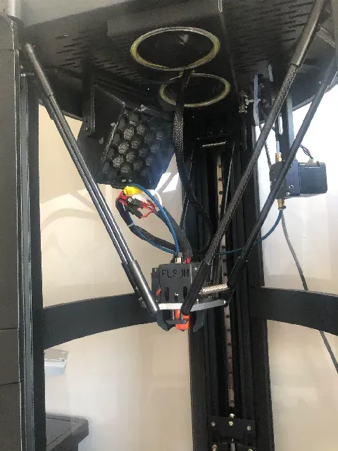
Unscrew the board and chip fan to mount the handle. The printed handle piece is attached to the roof of the printer using M3 screws on the bottom of the handle and secured with hex screws on the top of the grill. M3 screws are then used to attach the fan module with the holes on the side. Adjust the angle as you desire, and the second pair of m3 holes on the side can be used to add more grip or to adjust height of the fan. Thread the wire through the center hole of the ceiling and connect to the circuit. You should now be able to turn on the printer and flip on the fan toggle switch and everything should work!
I hope all this helps, if you have any questions or suggestions, leave them in the comments and I will try my best to get back. Thanks for the support and feedback I really appreciate it! :)
PARTS I USED
DISCLAIMER: (These are Amazon affiliate links, which means you can help support me at no extra cost to you if you make a purchase through these links.)
- https://amzn.to/3MaKqAv - Noctua Fan 80MM - https://amzn.to/3K1TRPN - 24V Buck converter (6 pack) - https://amzn.to/45JtbgH - HEPA + Carbon Filter 4"x4"x1.2" - https://amzn.to/3JVdpp6 - Round Toggle Switches - https://amzn.to/3GxEE8v - 5 Pairs of JST-XH 2.54MM Pin Connectors (Important to connect to printer power source) - https://amzn.to/3IgufxZ - M3 and M4 Screws I used (Comes with M3, M4, M5 screws of various sizes) - https://amzn.to/3YMRE0K - 8 mm Magnets I used (Comes with assorted sizes, so get 8 mm only if you don't need all of these for future projects) - https://amzn.to/40rbM9H - CCTREE PLA+ Black Filament. (Filament I used. Find any you like)




Названия используются только для указания источника результата. Polyzon не аффилирован с перечисленными площадками.