
Бесплатно 
Housing for USB-C Power Delivery module PDC004-PD
Printables

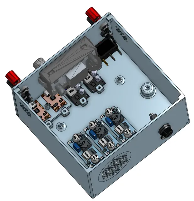




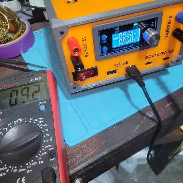
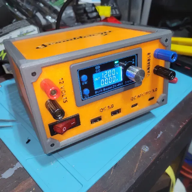
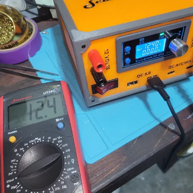
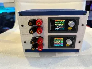
Scambler's Mini Power Supply utilizes those old laptop power packs you have laying around. This power supply chassis provides a wide range of outputs that include:
- 1 Variable banana plug output powered by a buck boost converter. - 1 constant 12V banana plug output. - 2 USB outputs that offer QC3.0 capabilities (12volt max) - 2 USB-C outputs that offer PD3.0 and Samsung's Fast Charging. These power packs generally only supply ~5 amperes so you won't be utilizing many of these features simultaneously but the combination of features allow for all your small electronic project needs.
I find this particularly useful for running my TS80 soldering iron and solder-fume fan as well as tuning all my buck converters before they are assembled into their various projects. I can even charge my phone, Bluetooth speaker or whatever.
The Components
Here you will find all the components I used to built this power supply.
- Filament. I used iiiDMax and Numakers for this project. I love these filaments. - 5.5x2.1mm DC power socket. - Fuse Holder . I added this as an extra measure of protection. Generally the power packs already have these safeguards built in. Still, a little extra protection doesn't hurt. I used a 10amp fuse. - Rocker Switch . I recommend a lighted switch as an extra power indicator. Just remember that you'll need a 12v DC switch. - LM2596 Buck Converter . This project uses 3 of them. - USB QC3.0 charging module. This project uses 2. - Type-C QC AFC PD3.0 charging module. This project uses 2. - Binding Posts . 2 positive, 2 negative. - ZK-4KX buck boost converter . - Hook up wire. I used 20 AWG. I wouldn't use anything smaller than 22 AWG on this project. - Ferrules . Use these to connect in the input and output on the ZK-4KX. As the owner of a 3D printer you should already have these on hand. But maybe not. - Blade terminals and U terminals . For your spade terminals you will want either the 4mm or 5mm depending on which screw you use for your common ground post. The chassis is designed for a 4mm bolt and all my proto-type used it perfectly. However, on my final build I forget to reinforce the number of walls for the hole in the slicer and it ended up too weak for 4mm. However, a 5mm worked just fine so I had to use the appropriate spade terminals. - Bumper Pads . Put these on the printed footings to prevent slips and slides. These are the same size used in #gridfinity bases so if you're utilizing that system you should have some on hand already. - M2 screws in 4, 6, and 8mm lengths. And M3 screws in 4mm and 6mm lengths. As a 3D printer owner you should have these but I linked the ones I used here for reference. - Superglue. Other Helpful Tools
Besides the actual components for the build, You'll need some additional tools. Some are necessary, some a great benefit to have. You'll need:
- A soldering Iron. I have several but I generally only use my TS80 these days. - Wire strippers and crimpers. - Heat shrink tubing. - USB Power tester . - A good multimeter . Buy quality here, this equipment will serve many purposes throughout your house, car and hobby. Printing
All the stl's were exported from the CAD in their assembled orientation so you'll have to adjust them in your slicer. There aren't any surprises here when it comes to printing and no supports should be needed on any of the pieces.
Some things to note:
- When printing the control panel you can add a filament change for the labels. The labels start on layer 13. - You need to print 4 of the stringer pieces. Position them so the 2 pegs are oriented upward. - The front and rear rail panels should obviously be positioned with the 4 spurs facing upward. - I provided .3mf file for the chassis footings as well as the .stl. With the .3mf file you'll notice that the bottom and top layers are set to 0 so the infill is exposed. However, the screw holes have been kept solid to allow a good purchase to the chassis. - If you choose to keep the Scambler 3D branded cover, you'll have to print the 2 small pieces that go inside the letter “a” and "b". These are then glue onto the inset logo piece, which itself is then glued to the cover. Assembly
The assembly has two parts: the chassis, and the electrical.
The Chassis
- The Cover - Print the cover, the inset logo, the two small logo inset pieces ("a" and “b”), as well as 2 of the stringer pieces. - Glue the “a” and “b” pieces on the logo inset piece; then glue the logo inset piece on the cover. - I glue 2 stringers onto the cover (aligning the tabs to the notches on the cover). But this is not a necessary step. - The main chassis - Print the chassis and 2 stringer pieces. - I glue the 2 stringer pieces on the chassis (aligning the tabs to the notches on the bottom of the chassis). But this is not necessary. - The footings - I glued the rubber bumper dots to the footings. I have found the adhesive on the dots to be rather suspect. The Electronics
This project requires a proficiency with soldering. If you're not very skilled yet, that's okay. However, I would certainly practice until you can solder well and don't leave cold joints. There are many YouTube videos on how to solder.
Tips:
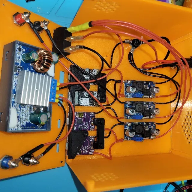
- Tin all your wires and module pads before final assembly. - Make your wires as short as possible without sacrificing workability. - It's easy to tune your LM2596 buck converters to 12 volts after they are wired up. However, tune them to 12 volts before wiring them to the USB modules. Mount these to the chassis with 4mm 3M screws. Assembling the electronics is relatively straight-forward. This design utilizes a Common Ground Post to connect all your ground wires. This helps easily manage your ground wires and makes assembly a little easier.
Remember that your three (3) LM2596 converters will need to be tuned to 12 Volts.
There are two tricky parts to this assembly:
- The middle pin of the rocker switch is your pos (+) out to the components. There are 4 pos (+) leads required. You could reduce this by wiring the LM2596 converters for the USB's in parallel but since we're only working with ~5 amps to begin with you want to provide every electrical advantage possible. To accommodate the 4 leads into the single blade terminal you'll likely want to solder the connection instead of crimp. I always solder my connections anyway so it wasn't a big deal for me. - When you connect the USB modules to the LM2596 converters you want the wires to be nice and short. Excess length in the wires will make fitting the modules in place difficult when closing the chassis. You might have to hot glue these module in place to help keep them from shifting while closing everything up. Use the following diagram for the wiring:
Final Thoughts
This is a pretty simple project that makes good use of old power packs. And while it is limited when compared to more robust power supplies, this little unit works great for projects with smaller power needs.
It's also a great first power supply project. Thanks to DroneBotWorkShop for the inspiration for this project.
The feet are a work in progress. They work and they're not really seen; so good enough for now.
If you like this project please consider making a small donation . As an Amazon Associate, purchases using my links help support projects like this.




Названия используются только для указания источника результата. Polyzon не аффилирован с перечисленными площадками.