
Бесплатно 
MK4 and muscled MK3 X-Axis Belt Tensioner
Printables
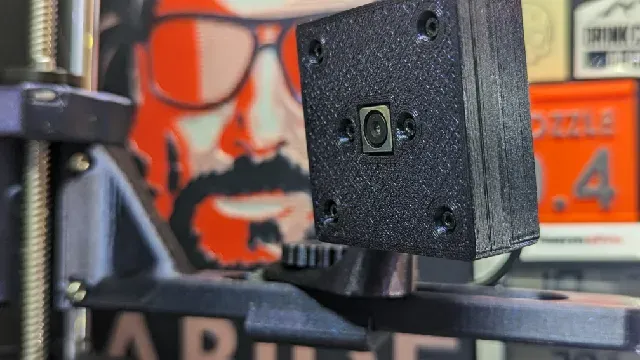
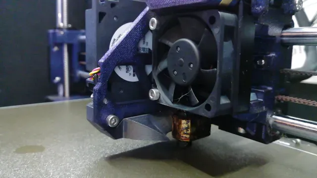


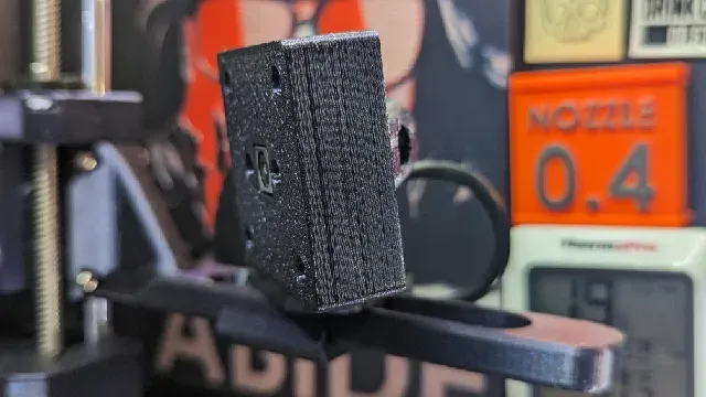
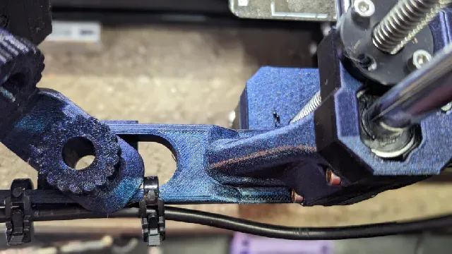

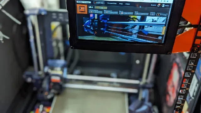
MK4 USB ARDUCAM 16MP IMX298 ADJUSTABLE X-AXIS MOUNT
After the MK4 upgrade, I considered using the same x-axis motor mount that I used on my MK3, but wanted to design something that would fit on either side of the axis, and provide more options for placement along the printer's y-axis.
Rather than remix any one of the (very good) options already out there for attaching things to other things, I wanted to design something from scratch, so I found the specs for my Arducam, and got to work. I haven't run into any issues with this model so far, but I'll update this with revisions if something comes up later.
Please notice that this design makes it possible to place the camera over a small edge of the print bed; if you have it fully extended, just check the alignment prior to doing any gargantuan prints that fill the build plate.
As with _ any_ camera mount on a moving part: make sure that there is nothing in the way of the full range of movement, and that your cable is sufficiently long to not restrict vertical motion or otherwise interfere with the printer operation
REQUIRED HARDWARE
- Arducam 16MP USB camera module ( the version without a metal case ) - Amazon (non-affiliate link) - OEM specs and documentation
- M2 screws/nuts - 4x M2x16 socket head hex machine screws - 2x M2x20 socket head hex machine screws - 6x M2 nuts - Any number of available M2 assortments contain a variety of sizes and enough to complete this and many other projects for ~ $10 You may also need a USB extension cable--the specified camera model comes with a 3.3ft/1m cable, which was too short for my enclosure setup.
Other camera modules may fit here, provided that they share the same circuit board dimensions. Here are the key specs I worked from ( and some related dimensions of the printed case parts ).
PRINTING INSTRUCTIONS
Three options:
- Use the included bgcode file - All parts are plated as needed, with supports and an orientation that printed cleanly and worked well for me - Sliced for MK4 (with input shaping) printing in PETG, 0.2mm SPEED profile -OR-
- Use the main 3MF file with all parts already plated -OR-
- Slice and print each file individually: print one copy of each object, and two of the screws (one to attach the camera and adjust vertical alignment, and one to attach to the arm and adjust slide/angle I printed mine in PETG to match my other MK4 printed parts, but you know your printer and your uses, so it's ultimately your call--anything suitably heat tolerant should be fine. Unless you're going ham on the screws, there shouldn't be any strains
POST-PROCESSING
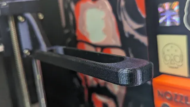
- Remove supports (as applicable) - For the arm, if you used supports on the Arm (where the x-end-clip has unsupported overhangs from the vertical orientation), they should remove easily if you dislodge them where the screw gets inserted, then push them out from the back using a screw or a small spudger/screwdriver.
- Check the thread fit between the two screws and their corresponding female threads. The fit may feel very tight the first time you tighten them, but they move smoothly after that, with enough friction to stay in place. If they're problematic after that, a little bit of PTFE super lube 92003 silicone grease on the start of the threads should enable easy movement ( this stuff is magic for any printed parts that directly interface, so it's very handy to have on hand anyway, and a little bit goes a long way--I've had a tube for years now without having to buy more).
ASSEMBLY
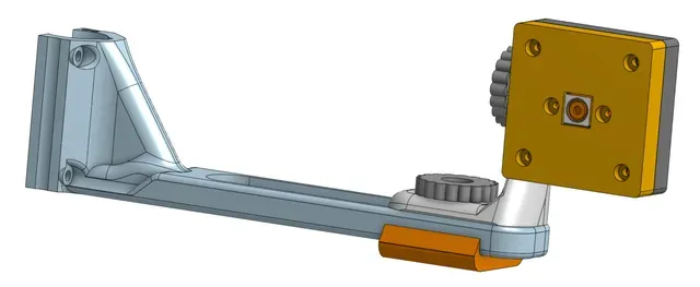
- Place the camera in the BASE part, with the cable slot on the opposite side of the onboard connector (as in the screenshot).
- Set the LID on the base, and attach it with the 4x M2x16 screws and nuts on the four outside corners. Put the 2x M2x20 screws through the two screw holes on either side of the camera lens, being careful not to drop them ( like me ).
- Slide the BASE CONNECTOR into the slot on the base, then drop in the last two nuts, and gently tighten the screws.
- Put one of the printed SCREWS into the top loop on the arm connector ( in your desired orientation--it works well either way, just remember to flip the video if you don't assemble it the way I've got it laid out here ), then screw it into the base connector.
- Place the last printed SCREW through the base of the arm connector, and then through the slot on the ARM. - Either orientation of the BASE CONNECTOR will work; I've tried it both ways, and it just depends on how you want the camera positioned
- Connect the ARM clamp, and gently tighten the screw - Remove the current x-end-clip from the MK4 x axis, and retrieve the pads from the original part, placing them into the same slots on the arm.
- Attach the arm the same way the original x-end-clip connected to the axis
- Connect the cables, and set up using the vendor's instructions
- Eat some gummy bears ( not included ), and post a make!




Названия используются только для указания источника результата. Polyzon не аффилирован с перечисленными площадками.