
Бесплатно 
MagDuct Parametric xTool P2 Exhaust Duct Adapter and Internal Fan Spacer (non-MagDuct adapter also included)
Printables




Motivation
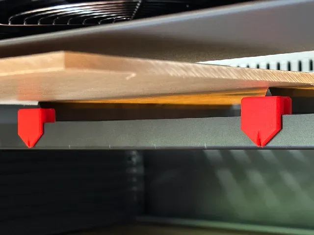
I recently purchased a P2 Laser Cutter and Riser. One of the first cuts I needed to make was on a long piece of ¼” acrylic to be used as a window insert to which I would attach the exhaust duct from my inline fan. I currently do not intend to buy the passthrough, but I figured I would be able to get this going in Baseplate removed mode. As I tried to set the acrylic up in the laser, I realized there was no way to position long workpieces level with the cutting plane of the laser using the passthrough capability of the riser. That capability was only made possible by the automatic passthrough…UNTIL NOW!
Solution
Design and print parts to accomplish the following objectives:
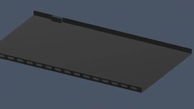
- Repurpose the P2 slats since they are already on hand, metal, and designed for this purpose
- Raise the lowest position to just inside the P2 laser’s maximum focal distance (75 mm) while maximizing the thickness of the material that can still fit in the riser passthrough opening
- Adapt to the existing geometry of the baseplate (it’s really Baseplate Lowered mode after all)
- Minimize movement once installed
- Provide a way to square up the slats with the baseplate as much as possible
- Allow for lateral (side-to-side), longitudinal (front-to-back), gridded, or randomly-placed installation
- Provide indices to align the back lip mount with corresponding marks on the baseplate back lip
Updates
v1.1
- New! Added a front index slot to more easily center the back lip mount on the baseplate back lip indices while standing in front of the P2 (previously alignment was only possible from the back).
Customization
The Fusion 360 file is attached. You can customize the parameters ( DESIGN | SOLID | MODIFY | Change Parameters | filter by the word “tolerance”) to suit your personal preferences or 3D printer’s tolerances. I designed and prototyped on a Prusa MK4.
Printing
See the attached .3mf for my settings. I recommend printing the front and back mounts with 5 perimeters for added durability. With the addition of the front index slot, I needed to add a modifier to ensure adequate bridging without supports.
Installation
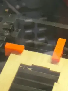
View both of the animated .gif’s.
The maximum material thicknesses are provided here:
These values were determined as follows:
- Minimums
- The slat risers place the top edge of the slats ~34 mm above the baseplate. I adjusted the values provided in xTool’s Riser Base article under the Process thick materials section by 34 mm. This means you can now process pieces <30 mm using the slat risers (with or without manual passthrough).
- Maximums
- P2 Slat Shelf – If your workpiece’s entire footprint remains without the footprint of the P2 slat shelves inside edge then the maximum is only limited by the P2 laser’s minimum focal distance. So, I just subtracted the same 34 mm to the maximum values provided by xTool in the same article above. Of course, for engraving, these will be more limiting than simply placing the workpiece directly on the baseplate but unavoidable for cutting. So, you can use Level 1 or just place the slat’s back in the P2 and “Process on slats” instead of using the riser at all.
- Passthroughs
- Back/Both – With the baseplate placed at Level 1, the slat risers place the top edge of the slats ~13 mm below the bottom of the P2 in the back. Each lower riser level increments this by 12 mm.
- Front – The bottom edge of the P2 is higher in the front than the back by ~18 mm. These values are increased accordingly.
The holes of the slat riser can be used in combination with a front mount to prevent lateral movement. The slat risers and rear mounts can also be used with dowel rods to construct a grid system or placed anywhere in the bed for a random arrangement or additional support. The current design is for dowels measuring 7.75 mm (.305”) in diameter, but that can also be customized using the SpacerRodDiameter parameter.
The P2RiserBaseplateBackLipMountStencil.dxf file can be processed (I used 1 mm thick clear acrylic) in XCS and used to translate the locations of the front ventilation slot centers onto the back lip (e.g. with a pencil or fine point Sharpie) for center placement of the back mounts.
Of course, you may still need to support your workpiece on the outside of the laser.
Questions
Please let me know if you have any questions ( Messenger | Printables.com ).
Shameless Plug
If this model helped you solve a problem, save some time, or in any way made your life a little easier then please consider clicking the Like button and posting your Makes! If it fell short after clicking on the title of the model, please let me know ( Messenger | Printables.com ). Either way, Thank you!
Related
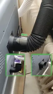
Complete exhaust configuration
Adapters - Convert machine exhausts to ducting diameter and/or MagDuct
- xTool P2 Exhaust Duct Adapter (configured as 4 in)


Названия используются только для указания источника результата. Polyzon не аффилирован с перечисленными площадками.