
Бесплатно 
Tensegrity Rubik's Cube Stand
MakerWorld

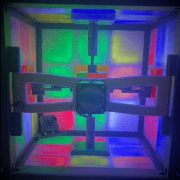
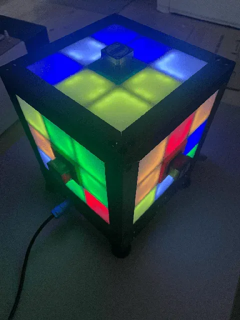

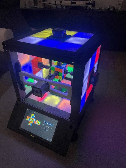
The record so far: 1.260 second !
Disclaimer
Despite being inspired by different robots, the model presented below is entirely from my imagination. It represents many hours of work. I am very happy to share it with you, but I ask you to respect my work, and not to forget to reference this design if you use it.
Abstract
Have you always dreamed of solving the Rubik's cube, but never succeeded? Then this robot is made for you! He can solve the Rubik's cube in less than two seconds! Yes, two seconds!
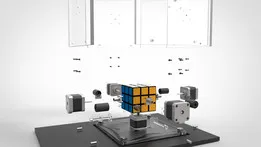
The robot is completely autonomous: it has a camera allowing it to scan the colors of the different faces. This step takes 6 seconds. Then, thanks to its six robotic axes, the puzzle can be solved in less than two seconds, whatever the starting configuration. The puzzle is surrounded by LED panels which imitate a Rubiks cube. They have two functions: the first, to ensure diffused and constant light during the recognition phase; the second: they allow you to reproduce the movements of the different faces of the puzzle while the motors move, thus producing hypnotic light animations.
The robot is almost entirely 3D printed, apart from the electromechanical components and the plexiglass panels, everything can be printed!
Thanks to the spring suspensions, the rubiks cube can easily be inserted and removed. Little extra, the front axle mounts on a pivot link, allowing access to the cube more easily.
The design was made in such a way that (almost) no wires are visible. All cables are routed inside the frame using integrated gutters. They are wide enough to contain the motor and LED cables.
Clearly, it's not the most useful robot in the world, but it does its job, and it easily impresses onlookers. In a science show, open days, or other gathering of nerds, guaranteed effect!
Units
Unless mentioned, all dimensions are in mm. This is also valid for the STEP/DXF files.
For the miscellaneous parts, I use DIN or ISO standards.
Print Settings
I printed all the part with a Prusa MK3S, using a 0.4mm nozzle, and 0.3mm layers.
All the parts are printed with the Galaxy Black PLA filament. I love this one, it gives a nice shinny effect that hides the layers, and make the plastic looking like metalic parts.
For most of the parts, the infill is set to a pretty low value (10-15%), but to ensure stiffness, the number of perimeters is always set to at least 3. If it increases the print time, it also drasticaly increases the part stiffness.
Building the machine
The transmissions
The transmissions are one of the very key components of the machine. They transmit the movement of the motors towards the faces of the rubiks cube. To set each face in motion, the transmissions fit inside the central facet of each face. They were designed for “SpeedCube” type rubiks cubes from the GAN brand. These cubes have much less friction, and are much more tolerant to the corner cut phenomenon (the fact that you cannot turn a face if it is not perfectly aligned).
As shown on the video bellow, the transmission can be locked in the unloading position. This enable easier installation of the rubiks cube inside the machine.
The transmission is mounted on the motor shaft thanks to a locking ring (DIN705) that is mounted by force inside the base of the transmission. The ring set screw allows proper mounting on a D-type shaft.
To ensure good stiffness of the transmission, an M3x40 screw passes through the transmission shaft to the interface with the Rubik's cube. Thus, delamination of the shaft is not possible, since the screw will recover the forces (like the pre-stressing with the concrete).
Transmission B.O.M
For each transmission you'll need the following parts:
Part Qty (total)
Base.step 1 (6)
Body.step 1 (6)
Piston.step 1 (6)
Interface.step 1 (6)
M3 Prevailing torque nut (DIN 985) 3 (18)
M3x40 Pan Head Cross recess screw (DIN 7985) 1 (6)
M3x20 Pan Head Cross recess screw (DIN 7985) 2 (12)
Shaft Collar - ID5/OD10/Thickness6 (DIN 705) 1 (6)
Compression Spring (0.9x10x40) 1 (6)
The side panels
The side panels have two main features:
- They host the LED strips creating the light animations - They hold the stepper motors, ensuring their correct positioning. You have to build 5 side panels, since the sixth motor is mounted on a movable frame.
The LED Arrays
The LED array will mimic the puzzle by creating a light show on all sides of the robot. To do this, I use the famous WS2812B addressable LEDs. These LEDs are really practical, inexpensive and simple to use. They reduce the number of electrical wires, while still being incredibly powerful. Each LED panel is broken down into 9 facets, exactly like the Rubik's cube. Only the 8 exterior faces are illuminated, the central face housing the engine. There are two types of exterior facets: corners (L-shaped), and centers (U-shaped). To facilitate programming, but also to have a uniform light, each facet has 6 LEDs. The corners are made up of 2strips of 3 LEDs, while the centers are made up of 3strips of 2 LEDs. The LED strips are simply sticked to the plastic arms, thanks to the integrated tape. At each location, raised lines allow the LED strips to be perfectly aligned.






Названия используются только для указания источника результата. Polyzon не аффилирован с перечисленными площадками.