
Бесплатно 
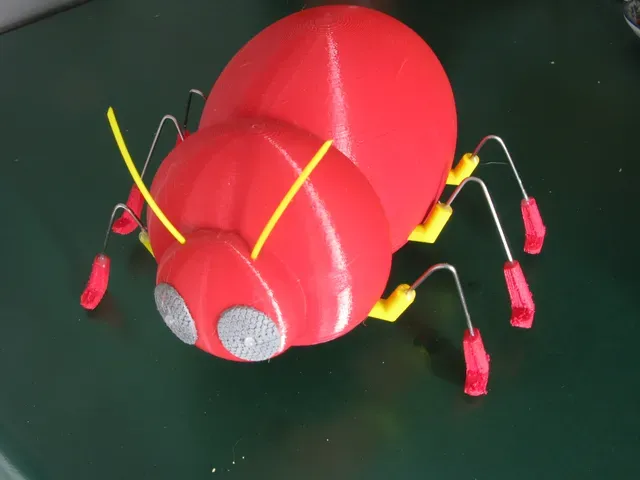
Walking Dinosaur Robot
Printables





Background
When I was a child (I am 80 now) I was given a clockwork beetle. You wound the spring up with a key & it walked along. I think it had 6 legs. I was intrigued by that toy. I am mechanically minded and have a university degree in mechanical engineering.
A while ago I bought a 3D printer (Prusa Mk3S) & learned Fusion. My final career move had been to own a Haas VF2 cnc machining centre & do contract machining plus use the machine for personal work. Notably I made a pendulum clock of my own design with a novel variation of the gravity escape as used on Big Ben. https://www.youtube.com/watch?v=KIyKBdWsWNE&t=4s I used an Israeli CAD/CAM program named Cimatron which was a DOS based program then with a graphical interface so it can be used in Windows. It is a very expensive commercial program so I did not do the annual upgrade so I was stuck on the 1996 version which was adequate for what I was doing. It is a wire frame CAD/CAM so no use for 3D printing. Hence I had to progress to Fusion.
I live in Cape Town but my daughter and her family live in the Netherlands. They are coming to visit in August 2024. I set myself the target of making a walking beetle on my 3D printer to show my grandchildren. I know little about electronics so decided to buy a remote control toy vehicle & extract the electronics from that. I found a RC drift car to fit the bill https://www.takealot.com/360-double-side-roll-rc-stunt-car-flashing-light-blue/PLID66382548
That toy has four electric motors. I use just two of them. I designed & made the beetle; had to do some revisions to get it satisfactory. It was a nice challenge which I much enjoyed tackling.
Beetle Legs.
The legs of an insect all originate from the thorax with the abdomen behind as shown in the picture of an ant.
<< Embedded picture does not come through >>
Here is a drawing of a scarab (= dung beetle = scientific name Scarabaeidae) apparently showing two pairs of legs sprouting from its abdomen.
,, Embedded picture does not come through >>
In fact the first bits of the middle and hind legs sprout from the thorax but they run backwards and are fused to the underside.
I have had to use the dung beetle layout in my mechanical beetle. I have had to also add a tail wheel. The drive gears, battery and motors are behind the middle legs so when the rear legs are raised and are moving forwards the beetle tips on its middle legs and the tail wheel supports the weight and prevents it tipping any further. I tried adding a counterpoise weight ahead of the first legs but it needed to be heavy and spoiled the walking ability of the beetle.
Beetle Walk
Beetle have six legs. Their walking is called tripod gait. Three feet are always on the ground. Front & hind on one side and mid leg on the other. Each row of legs walk just like we do; one is on the ground moving “backwards” while the other is off the ground moving forwards. The front & rear legs are always in step and the middle leg is always out of step.
Spiders have eight legs but they walk just like insects except they have an additional row so they always have four legs on the ground. Rows 1 & 3 are in step and rows 2 & 4 are out of step with the other rows.
Centipedes & millipedes use metachronal wave walking. This site has nice gif of the way it works https://www.nablu.com/2022/12/metachronal-waves-of-legs.html The second gif shows the gait that I use on my beetle. Again each pair of legs walk as we do; one up & the other down. The movement of my beetle legs is controlled by separate cams for each of the 6 legs. Numbering the legs 1, 2 & 3. Leg 1 foot down at 0° of the cam. Leg 2 foot down at 120° and leg 3 down at 240°. Each leg is down for 180° so from 120° to 180° 2 legs are down. From 180° to 240° only 1 leg is down. It turns out that with 3 pairs of legs each 60° it changes from 1 to 2 (or 2 to 1) on each side.
I find that the beetle walks better with the progressive walking than the tripod walking but you can assemble the cams to do either. In the assembly instructions I describe the progressive walking assembly. If you want tripod walking set cams 1 & 3 in phase and cam 2 out of phase (1 & 2 up while 3 is down). Both cams rotate anti-clockwise when the beetle is walking forwards.
In live beetles each pair of legs are synchronised (out of step). In this mechanical beetle there is no such synchronisation.
Video Beetle doing tripod walking https://youtu.be/v-IzK3sr5_Y
Video Beetle doing progressive walking https://youtu.be/ow1dIUSqjTk
Materials
Drift car RC toy. See background. Cam shaft. Ø4 steel rod. 2@ 121 long Gear shafts Ø3 steel rod. 4@ 27 long Legs Ø1.6 stainless steel TIG welding rod. 6@ 120 long Vaseline = petroleum jelly Rubber bands 3mm wide (1/8”). I could not get silicon bands locally so used natural rubber bands. I understand the silicon rubber bands are superior. Super glue Epoxy standard set glue. Epoxy rapid set glue. M2 x12 cheese head screw, nut & washers: 2 M3x10 cap screws & nuts: 11 M3x12 cap screws & nuts: 7 M3x16 cap screw: 1 M3x25 cap screw: 1 M3x35 cap screw: 1 M3 nyloc nuts: 4 M3 square nuts: 2
Tools See Assembly\Motors & Electronics – the wire stripper & terminal crimper are not required if you are methodical.
Wire stripper. Needed to strip the thin wires between control board & the motors. I used Chinese copy of the Irwin stripes in this article. https://www.popularmechanics.com/home/tools/g39663063/wire-strippers/#product-bce2739a-b1be-46f5-af85-34242d5fd69d
Terminal crimper. Terminals are needed on the wires so they can be joined or insulated in the wire connectors. I used this tool but at a much lower price from a local supplier. https://www.amazon.in/DeHMY-Crimping-Terminal-Crimper-HSB6-4/dp/B0BDBSHB23
M3 cap screw screwdriver. I made a handle for the usual ball end hockey stick style Allen cap screw tool. It makes assembling the beetle much easier. I have posted it on Printables. https://www.printables.com/model/928091-allen-key-screwdriver-style-handles
Assembly
Motors & Electronics. The drift car has 4 electric motors. We use only 2 motors. The motors are mounted on the top of the drive frame with the 10 tooth pinion facing the head of the beetle. Viewed from the back of the beetle the motor must turn clockwise. Then the cam will turn anti-clockwise & the beetle will walk forwards. To match the remote control so Left button Up makes the beetle walk Forwards both motors should turn clockwise when viewed from behind. I found that I must use the motors with Blue & Yellow and Blue & Red wires. Be safe & determine which of your motors will turn clockwise when viewed from behind with the left button on the RC pushed up. Choose those 2 motors & you will not need to cut the wires and life will be easier. So the motors with Green & Yellow and Green & White are not used. So use motors with Blue wires & eliminate motors with Green wires. I cut all the wires but I recommend not doing that. Cut only the wires to the 2 motors that are to be eliminated. Then insulate the cut wires so they don’t short. I had to do that by crimping on terminals & securing them in the wire connectors. It will be much easier to fit the motors & control board if wire connectors are not used. If the motor wires are not cut then there is no need for the wire stripper and crimper. You can insulate the wires of the 2 discarded motors with insulation tape.
Floor. Insert 2 M3 square nuts into front Cam pedestals. If you don’t have square nuts the slots are deep enough for regular nuts to be used. Square nuts resist turning well which is why I chose them. M3x10 cap screws into them. 2@M3 nuts into tailwheel spigots 2@M2 nuts. Draw in usingM2x12 screws with washers
Hip Clamp. Insert 7@M3 nuts. 3@M3x12 into the rubber band clamps & fit them loosely into the nuts 3mm rubber bands. Cut 150 long piece. Overlap the ends to make a 57 flat loop (both sides touching, so circumference = 57*2 = 114), stretch the overlapped piece & fit under the rubber band clamp & clamp it there. See photo.
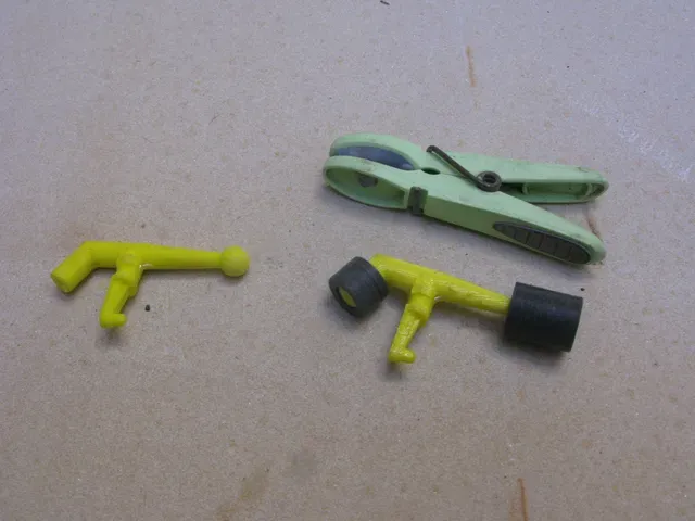
Hips. Glue the 2 halves of each Hip together. Super glue. There is a cylindrical jig that fits over the ball and a short tubular one that fits over end where the wire fits in. Use those to hold the two parts together. Use a clothes peg (or similar) to hold the cam follower arm together. When the glue has set clear the wire hole with a 2mm drill.
Legs. The legs are made of 1,6 mm TIG welding stainless rod. Bend & cut them on the leg jig. Trim the TIG rod to match the jig. Glue the wire legs into the Hips. Quick set Epoxy. Smear each hip ball with Vaseline (petroleum jelly). It is cleaner than grease.
Floor Smear Vaseline on the Hip guides (the little square pillars at each Hip slot. Place the Hips in the slots. They are numbered. Fit the Hip Clamp over the Hips. Secure with 4@M3x10 cap screws. Check that the Hips move freely Fit the rubber bands over the Hips. There is a groove that they fit into.
Cams. The cams and the torque tubes that join them have a spiral groove inside them. That is to hold Vaseline to act as a lubricant. Using a small screwdriver put some Vaseline in each piece & use the steel shaft to spread it into the spiral groove. Assemble the Cams. The Cams are numbered. There are two timing options; Tripod or Progressive. Progressive is better. Cam 1 has a timing mark on its rear face. Cam 2 has a timing mark on its numbered face. Fit the plain torque tube so those timing marks are in line. Cam 2 has a timing mark on its un-numbered face. Fit the other torque tube into cam 2. Slide Gear 6 onto the torque tube. Slide the spacer onto the torque tube. Cam 3 has a timing mark on its numbered face. Fit it to the torque tube so the timing marks are in line. The steel cam shaft is Ø4 x 121 long. Grind a short point at one end so it finds the holes in the pedestals easier. Grind a flat 10 long at the other end for the lock screw to seat onto.
Cams into Floor. Slide the assembled cam between the pedestals on the floor and insert the steel shaft from the front pointed end first. As you do this ensure that the cam follower fits into the cam groove on each cam. Make sure the flat is facing upwards. Tighten the lock screw. Smear Vaseline into each cam groove. Rotate the cams by hand forwards and backwards a few revs. Repeat the Vaseline treatment but 180° from the first so as to get the entire cam groove lubricated. Lock shafts into place with M3x10 cap screws.
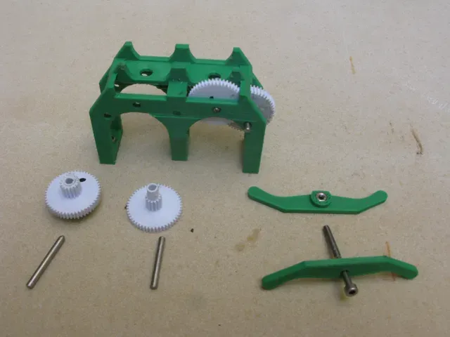
Drive. Fit 3@M3 nyloc nuts into the bottom of the legs of the Drive Frame. Fit 1@M3 nut into the underside of the top of Drive Frame Fit 1@M3 nut to the shaft retainer of the Drive Frame The gears have a spiral Vaseline groove in their bores. Put some Vaseline in them The gears are numbered 1 2 3 4 5 6. 1 is on the motor. 2 &3 are printed as a unit. 4 & 5 are printed as a unit. 6 is on the Camshaft. Fit 2&3 into the Drive Frame in the top holes. Insert the shaft Ø3x27 with a short point ground on one end so it finds the hole easier. Fit 4&5 so that 4 meshes with 3. Insert the shaft. Do the other gearset. Fit the shaft retainer 1@M3x35 cap screw. Fit the Drive assembly onto the Floor 3@M3x10 Turn gear 2 with your thumb and feel how the gears are meshing. There is a tight spot just as the follower reaches the end of the rise. If you clamp the drive frame hard against the floor then gear 5 may be pressed too tightly into gear 6 on the camshaft. That is why nylock nuts are used. You can loosen the outside cap screw 1 rev & the middle cap screw ½ rev & lever the frame away from the floor with a knife (Leatherman) to ease the gears apart. In my case I have to back off just the left side 1 ½ turns for it to run smoothly
Motors. Fit motors onto top of Drive frame. Wires & capacitor (?) face downwards. Gears 1 & 2 centered. Clamp them in position with the motor clamp. 1@M3x25 Mount the Control board 2@M2x12 with washers. Fit the battery. Note: If your control board does not have the mounting holes in the same position then make an intermediate board that can be attached using the provided holes which has additional holes so your board can be screwed to it.
Tailwheel. Fit Tailwheel in the clevis 1@M3x16 & nylock nut Fit Tailwheel to Floor. 2@M3x10
Boots The distance from the bottom of the boot to the underside of the floor is critical for the Beetle to walk properly. In the photo I have the floor resting on a roll of packaging tape. Legs 1 & 3 are in foot down at mid stride. I have 3 playing cards between the beetle floor and the roll of tape. That sets the distance from the top of the block of wood to the underside of the floor to 28.2 mm. That is the correct distance (+- 0.5). The bottom of the tailwheel is 2 less (26mm). When you have the distance correctly set make sure the Hip is vertical (mid stride) and on the high part of the cam (foot down). Slide the boot onto the leg wire & make sure it will fit at the correct position. Then glue it into place. I like to use standard set epoxy as that takes 12-24 hrs to set so there is no rush. Smear the glue onto the leg & slide the boot on. I take it off & smear the glue again so I am sure it is properly in the boot. Once you have boots on legs 1 & 3 you can turn the cam so leg 2 is down at mid stride & glue those boots on.
Bodywork. Glue the eyes to the bodywork. Use the LED guides to center the eyes on the holes in the bodywork so the LED lights can be fitted. Guides are not glued to either the eye or bodywork. If you are going to fit the blue LED eye lights you need to make the wire longer. The original wire is nice and flexible. That helps when you fit the connector into the control board. The connector has 2 little square lock pins which I cut off (Xacto knife) to make fitting & removing the connector easier. I hot melt glued the wire along the inside top of the bodywork. The bodywork & the wire insulation are plastic so they will be softened by the hot melt glue so use the glue as soon as it can be triggered into place & don’t use much. Before fitting the bodywork turn the cams so Hip 1 is pointing straight up on the foot lifted portion of the cam. That gives the most space for fitting the bodywork. Slide the bodywork onto the assembled beetle. Gear 4 are slightly wider than the Bodywork so you have to ease it past them. Then fit the bodywork onto the floor doing the front first. Secure with M4x10 cap screws Antenna. Use Ø1.75 filament.





Названия используются только для указания источника результата. Polyzon не аффилирован с перечисленными площадками.